A viable and proven method to replace rotary drills for deep drilling using sequential capsulized explosive vertical bore penetration technology.

Christophe de Rivals-Mazères Engineering, Residence Olbius Riquier Entree B, 11 Chemin du Martinet, Hyères-les-Palmiers , 83400 France. Contact: Mobile: +33 6 11 79 97 85

Note: Explosive drilling is not an really invention, it is an old technology initially proposed by the Soviets in the 1950s. Christophe de Rivals-Mazères Engineering, in its knack for identifying ignored, missed, or abandoned opportunities, improved upon it by making a number of important contributions. Starting with the choice of over-pressurized gas as a working fluid rather water, employing a suction based spoil removal method, and using solid rather than liquid explosives. These three design changes should be overlooked as mere trivial options, they are fundamental to the viability of this unique technology. The original developers of this otherwise sound concept faced issues that are solved by the implementation of these three design options.

Brief introduction: Christophe de Rivals-Mazères Engineering, has revived a long-forgotten technology by making a number of improvements to the fundamental process, resulting in a new and powerful method to excavate rock without having to resort to technically challenging melting or vaporization methods. Capsulized insensitive solid explosives mass produced for only a few dollars per kg are fed into a shaft encased within the drill “string” and detonated upon the force of impact. Spoil removal is performed using a highly novel suction device within a gaseous over pressurized drilling media. The use of a gas at a pressure above the background water pressures retains the advantages of oil or water based fluids in preventing the influx of unwanted liquids, but allows for much improved fragment recovery and hugely drilling speed. After each detonation, a suction nozzle that generates a 1-2 bar pressure drop is descended into the fragment bed to rapidly evacuate the fragments generated from the previous explosion. While the method is not necessarily cheaper in terms of up-front costs than current technology, it can perform for a longer endurance period without bit replacement and it can penetrate trough hard rock in the brittle-zone at least 10 times more than conventional diamond bits using down-bore motors. The average drilling speed of a diamond bit down-bore motor drill in hard crystalline bedrock is 2.3 meters per hour, this method can excavate as much as 100 linear meters per hour as long as the rock does not yield plastically. The method is most productive in the hardest rocks, exactly where geothermal resources are most propitious. Out of all the present drilling concepts put forward, this is by the most likely candidate to enjoy commercial success on the basis of its simplicity and the maturity of the underlying methodology Compared to the “Plasmabit” marketed by the Slovakian company GA drilling, or the “millimeter wave” drilling system proposed by Quaise, explosive capsule drilling is the most viable for a up to 12 km crystalline rock drilling technology. Issues with thermal degradation, molten rock accumulation, inefficient energy delivery, among many others, handicap thermal drilling systems for the foreseeable future. This leaves us with novel mechanical disintegration methods. Among mechanical means, explosive drilling is simply without peers. Chemical high explosives possess the greatest density of storable kinetic energy of any known technology other than nuclear weapons. Their ability to release immensely high velocity pressures waves afforded unparalleled destructive facility.

Summary and key findings.

#1 Explosive capsule drilling to this day remains the only successfully tested alternative to rotary bits. Other alternatives such as microwave vaporization face a number of potentially insurmountable technical problems.

#2 High flow water cooling can maintain explosive capsule temperature at 100°C or below keeping decomposition to a minimum. Geology, rather than temperature, place a feasible upper limit of 12 km due to the brittle-plastic transition zone encountered which causes rock to plastically yield, causing well cave in and making explosive fragmentation ineffectual.  

#3 Contrary to assumptions made by Maurer, it is not cost or safety that limits the technology but rather the issue of using explosives in traditional liquid based drilling fluids, which due to their incompressibility, transmit pressure waves very long distances. The crucial problem to solve is spoil or fragment removal and this will ultimately determine drilling speed and overall viability. By employing a retractable and extending flushing nozzle, high velocity liquid can be sprayed directly in the fragment bed alleviating poor removal, the problem of fragment accumulation has therefore largely been solved on a conceptual basis. Unfortunately, providing close proximity to fluid exit is not sufficient, one the particles exhaust their momentum, they will fall back down. The use of a high viscosity preferably oil-based fluid is essential if not required for successful operation. Thankfully, engineering options exist to permit high viscosity oil based fluids to be used without decomposition or excessive losses.

#4 The critical design feature of the explosive drill is a water-cooled annular sleeve that slips along the well-bore wall to cool the incoming fragment containing oil. The use of actively engaged packers can adequately prevent excessive mixing of oil and a layer of water between the wellbore wall and the annular water cooling channels.

#5 Pumping powers in excess of 10 MW is required, around 5x more than rotary drills due the need for higher viscosity drilling fluids and a large amount of coolant 

#6 Drilling speeds as high as 100 meters per hour are feasible in hard crystalline rock using suction spoil removal.

#7 Safety is not expected to be an issue with phlegmatized explosives and the use of heavy-duty shockwave attenuation systems at the surface.

#8 Explosive costs are not a limiting factor, the costs saved by eliminating the drilling fluid and the massively improved productivity offset the added costs of explosives by a substantial margin.

#9 Explosive drills are ideally suited for penetrating large diameter wells which opens up the possibility of novel-down-bore well fissure stimulation using chemical or nuclear explosives for goethermal power extraction.

#10 The technology cannot be used for in soft, plastic rocks typically found in the sedimentary layer.

#11 Explosive capsules can be detonated by using the force of their impact with the rock bed or timed slapper, mechanical percussion, or shock bridge detonators using small batteries.

Introductory Q&A

Why do you think explosive drilling is superior out of all the potential options?

Answer: Because no currently viable replacements to bit-based drilling exists outside of explosive and projectile drilling. Explosive drilling is not chosen due to some intrinsic attachment to the concept on behalf of its developers, but due to the lack of viable alternative options and the sheer fact that it appears immensely attractive from a number of technical standpoints. Presently marketed alternatives, namely so-called “millimeter wave” is plagued by technical issues, leaving explosive drilling and high velocity projectile drilling as the only solutions. Since high velocity projectiles do not sufficiently fracture rock into small fragments needed for satisfactory spoil removal, it is stuck as a “hybrid” option, requiring conventional drill bits to paired to the system.

But explosive drilling is not new, wasn’t it tried before and not developed due to cost and safety reasons?

Answer: The definition of “new” is problematic. The diesel engine was not new as a heat ignited reciprocating engine, Aykroyd engines achieved thermally induced ignition before diesel, but the precise methodology of igniting fuel purely by hot air was. Explosive based drilling is a principle, not a technology. It is a methodology, but in order to built a working system, a number of technical details have to be sorted out. One such detail is effectively flushing rock fragments out. Previous attempts at explosive drilling experienced difficulty doing this because the nozzle had to be held up to 500 millimeters above the rock bed, debilitating the fluid’s removal efficiency. Christophe de Rivals-Mazères Engineering, has circumvented this problem using an electromagnetically actuated rapidly retractable and extendable nozzle that sprays drilling fluid directly into the rock bed after explosions in a cyclical process. Another solution is the use reliable, melt cast metal cased phlegmatized solid explosives fired from the nozzle using combusted fuel and oxidizer in order to reliably detonate them upon impact. Previous explosive drills, namely the Russian one, used leak prone sensitive liquid explosives with complex mixing mechanisms or solid explosives but with sensitivity primary explosive as detonators. These solutions make this technical realization of explosive drilling meat the definition of “new”. Lastly, cost and safety not genuine limitations, explosives such as cyclonite can be synthesized for a few dollars per kg using formaldehyde and ammonia as the only feedstocks with intermittent wind or solar power. Formaldehyde is produced by the catalytic oxidation of methanol. Safety concerns can be quelled by using a highly robust blow-out prevention device to isolate personnel from the effects of shockwaves emanating form the borehole if some of the capsules accidentally go off.

But without a prototype how can you be certain that your design improvements will solve the previous issues encountered with this method?

All technologies are begin their developed course on the drawing board according to our present knowledge of science.

William C Maurer has largely endorsed explosive drilling, while he did not endorse high velocity projectile drilling, claiming such a methodology would not work in narrow and deep petroleum and geothermal wells.

The efficiency of explosive charges increases with fluid pressure, indicating that this explosive drill would be most effective in deep wells for which drilling costs are high. Efficiency also increases with explosive charge size, which suggests that a full-scale drill would be more efficient than the charges used in these preliminary tests. No attempt was made to optimize the explosive charges in the tests, so considerable improvement could be expected on a detailed development program”.

This Soviet explosive capsule drill is of special interest because it has been thoroughly field tested and has shown that it can effectively drill holes at fast rates. This drill can penetrate nearly all types of rock and has the advantage of high power output. Its main limitations are that it will not effectively drill soft materials such as clay and that the cost of the explosive capsules is quite high since they are consumed at rates up to 720 capsules per hour”.

Introduction: Accessing the crust’s great depths represents a great leap forward in man’s knowledge of the geology of the earth as well as providing nearly unlimited energetic and mineral resources. For example, presently, gold cannot be mined deeper than 2000 meters due to temperature constraints on men and materials and limited cooling options. With explosive drilling, large multi-meter diameter wells could be drilled in existing gold deposits accessing tens of thousands of cubic meters of rock at great depths ready to be sifted for gold, silver, and platinum group metals. Unlike milli-meter wave drilling, explosive drilling is scale invariant and could easily scale to permit drilling massive diameter well-bores deep into the earth to access exotic elements. Modern civilization, in spite of its prodigious technologies capacities, finds itself helpless when it comes to reaching the deeper regions of the upper crust. This baneful condition results in an incomplete understanding of the crust’s geology, its mineral composition, and most importantly, it leaves civilization stranded scourging the shallow sedimentary deposits for critical resources. It also prevents man from accessing gargantuan deposits of medium grade heat than could, provided fracture stimulation methods are develop, permit man man to generate electricity for less than the cost of oil and natural gas. Developing improved methods of fragmenting and extracting rock to great depths in a continuous process is an essential task for engineering in the 21st century. Christophe de Rivals-Mazères Engineering, views itself as bringing to market an old but updated technology that has long been ignored. This technology is the use of packaged charges of the most explosives fired from a down-bore nozzle to fragment rocks into millimeter size particles easily removed by high lift capacity water-based drilling fluids. A series of improvements are made from the original demonstration of the technology.

A few statements should be made. The term “drilling” should be dispensed with since most of these alternative methods make no use of rotary grinding motion to remove rock. In fact, most if not all of the alternative, “novel” or “advanced” drilling techniques chronicled in William C Maurer’s book deal with methodologies that are inherently “bitless”. Regarding the proper choice of terminology, despite the fact the term drilling fails in properly defining the underlying methodology employed for rock disintegration, the word “boring” is connately redolent of tunnel boring, and even through we would like to dispense with the world drilling, it will still be used for search engine optimization purposes since most prospective customers, engineers and technology developer will continue to employ the conventional vocabulary. Despite its floundering performance in deep and hot crystalline rock, conventional bit-based abrasive rotary drilling technology has must a number of strides over the past century. Starting with rudimentary percussion bits which were dropped into wells using the force of gravity, and concluding with the state of the turbodrills used in ultra-deep methane wells in Siberia, to the horizontal drills exposing shale rock in the Permian basin. The percussion drills of the late 19th century and early 20th resembled a chisel, and despite being very simple and inexpensive, the device would wear out very vast and penetration rates were exceedingly slow. It was not until the early 1900s rotary bits were finally developed, with the famous Hughes roller cone bit completely revolutionizing the oil industry and making petroleum extraction a viable technical endeavor for the time. In fact, one could argue that the Hughes roller cone bit was the single most valuable patent of the early 20th century. But drilling innovation did not stop here, in the 1920s Soviet engineers developed the now-standard turbodrill. Despite the turbodrill’s powerful advantage: negating the need for a drill shaft, a number of innovations in bearing, seal, and gear technology were needed before the turbodrill could be made viable. Early turbodrill blades suffered from rapid erosion, leakage, and short reduction gear life. Advances in turbomachinery design and metallurgy eventually eliminated these challenges making them highly reliable. Once these advancements were made, turbodrils soon surpassed shaft-driven drills in penetration speed and even reliability. One of the key advantages of the turbodrill is its ability to drill much deeper than shaft drive drills, since shaft binding against the bore-wall is not an issue. But by far the most important advantage it its ability to drill laterally, paving the way for the “horizontal drilling” revolution that recently boosted U.S oil production after decades of decline. Ever since this early Soviet invention, Russia has continued to manufacture and engineer the world’s most advanced turbodrills. In its insatiable quest for more advanced drilling technology, Soviet Russia also began developing electro-drills, with downhole electric motors in the 1950s, but poor motor power density and weakly designed power delivery cables limited the technology at the time. With much better microelectronics that can deliver high voltage power to rectifiers into low voltage AC or DC feeding high power density, electrodrills warrant serious consideration even if bit technology is the limiting factor. Despite this, turbodrills remain the mainstay of deep drilling to this day and account for the bulk of horizontal drilling.

Rock boring, whether it is to construct a tunnel in the Swiss Alps or to drill a well for oil and gas, is perhaps one of the most challenging engineering endeavors man can undertake. A combination of the extreme temperatures encountered at the ten-kilometer range, the immense hydrostatic pressure which compresses water to tens of thousands of psi, the sheer hardness of the crystalline rock, and the enormous distance to the surface, culminate to yield a vastly challenging technological demand. An amusing comparison is the fact that its easier to launch a rocket into orbit than to drill an ultra deep well in the crust. Presently, for the price of sixty million dollars, a multistage launch vehicle using kerosene and liquid oxygen can reach geostationary orbit 36,000 kilometers away with 99% reliability, while the best drills in the world can barely penetrate 12 kilometers while taking years to reach this depth. Of course, the comparison is purely illustrative, it is by no means technically homologous. A rocket, once it has expended its fuel mass is simply soaring through empty space with hardly any drag. Then all it has to do is decouple its payload and effectively “dump” it into orbit. The task is momentous and impressive no doubt, but it is surprisingly simple. The greatest challenge faced by designers revolves around ensuring that the propulsion system, highly flammable fuel, does not leak or ignite especially during takeoff. Stage decoupling has become a streamlined process with few hiccups, and guidance, with the introduction of inertial gyroscopes, has proven surprisingly simple. A rock boring machine on the other hand has to spall, fragment, disintegrate the solid extremely hard mass in front of it, all while ejecting this mass back up the hole that is barely bigger than the unit itself. Add in temperature, pressure, and the weight of the shaft or cable that must suspend this entire device plus bear its own weight, and we have a task that greatly exceeds the difficulty of “rocket science”.

But the overall message is clear, what stops us from boring holes at even conservative depths of 12-15 km? Is there any fundamentally physical, chemical, metallurgical, or overall technical factor that simply prohibits us in much the same way we are forbidden from building airplanes with lift-to-drag ratios much over 20 due to the laws of aerodynamics? The answer is yes. As we’ve mentioned before, the fundamental issue that is not receptive to engineering solutions is not heat or pressure, but the change in the rock’s physical properties.

A way of ascertaining the degree to which a present technology can be potentiated is by analyzing the extent to which there exists a noticeable gulf between the desired performance and the demonstrated performance. The gap between technological expectations and actual performance determines how mature or how much potential there is left for improvement. The intensity of environmental attrition. This metric can be used to gauge how susceptible a particular technological complex is to outside factors which cannot be appreciable attenuated. Such an example is the drag acting on a train or the friction that its wheel incurs, or the impact damage should the train hit a vehicle. Engineering can improve the power of the electric motor, the power transmission system, or the vehicle’s durability, but it cannot eliminate these exogenous antagonists. In the case of a bore-hole penetration system, one cannot engineer a device to make the rock strata softer, but one can undoubtedly make a more potent rock destruction apparatus. 

Using this metric, drilling technology is either handicapped by some ill-defined but likely highly persistent performance boundaries that are difficult to overcome, determined mainly by concrete physical, thermal, abrasive and material challenges, or there is immense work yet performed to potentiate it. If the latter is the case which we believe to be true, there exists immense upside in performing the necessary R&D not to mention commercialization of the first alternative to the rotary bit for a over a hundred years.

Any alternative drilling or bore-hole penetration system must fundamentally remove rock either by mechanical force or heat. Mechanical force can use abrasion, kinetic energy, extreme pressure, percussion, etc, through a variety of means to achieve said mechanical force. The second category is thermal, which has never to this date been utilized except for precision manufacturing such as cutting tiles or specialized materials using lasers. Thermal borehole penetration is evidently more energy intensive, since rock possesses substantial heat capacity, and any drilling media, whether gas or liquid, will invariably consume a large portion of this heat. This heat must then be introduced somehow, it can either be in the form of combustion gases directly imparting this heat, which in that case the combustion can occur only at the tip, with the transport mechanism being the movement of the combustible compounds in liquid or gaseous form. Alternately, intermediate mediums of delivering thermal energy such as lasers, plasma, or some form of high-frequency radio wave. Plasma can be generated at the tip by passing electrode current from two electrodes. The energy of a very powerful laser can be introduced via a fiber-optic cable and emitted at the tip. Regardless of the technically feasible of the various thermal penetration concepts, they all share one feature in common. The last method available is chemical, in which strong acids may dissolve the rock into an emulsion that can be sucked out. This method is limited by the high temperature of the rock which may decompose the acid and the prohibitively high consumption of chemicals which will prove uneconomical.

Any drilling concept which relies on thermal energy to melt, spall, or vaporize rock is ultimately limited by the fact that it cannot practically use water as a working fluid, since virtually all the energy would be absorbed in heating the water. Additionally, thermal methods such as lasers will incur very high reflective and absorptive losses from rock powder and even micron thick layers of water on the rock bed. Regardless of the medium of thermal energy delivery, be it radio frequency, visible light such as in a laser, or ionized gas, that is plasma, will be greatly attenuated by the presence of the drilling fluid, requiring the nozzle to be placed just above the rock surface, presenting overheating and wear issues for the tip nozzle material. Hydrostatus System’s concludes based on extensive first principles engineering analysis that thermal systems will possess an assortment of ineluctable technical difficulties severely limiting their usefulness, operational depth, and practicality. Our conclusion is that various means of mechanical disintegration, through a combination of pressure, velocity, and force will remain the method of choice for excavating boreholes far in the future. Since mechanical force is the method of choice, we must now narrow down our choice in identifying the optimal means of imparting this mechanical force to the rock media. We have at our disposal plain mechanical action, such as using percussion or rotary force, but these means are quickly ruled out due to lacking force delivery intensity. We are left with the last option, using high-velocity projectiles, but we have ruled out this option due to the availability of an even better alternative: detonation of energetic materials. Energetic materials are a class of nitrogen rich molecules which possess inherent instability due to their strong tendency to oxidize upon stimulation. Energetic materials are class of propellants, explosives, and regular heat releasing deflagrating compounds, colloquially known as fuels. Should explosives not exist, we would undoubtedly employ the option of high velocity projectiles.

For those that are interesting in developing advanced deep hole boring technology for applications other than oil and gas, “heat mining” is the prime candidate. For those unsatisfied by terrestrial energy harvesting schemes, be they solar or wind, it seems only obvious to the astute energy engineer to look down upon the crust for heat. The mantle is a block of molten iron and nickel whose heat emanates from the radioactive decay of thorium, uranium, and other trace isotopes. But heat does not only emanate from these decaying isotopes as they form lighter elements with a mass deficit, yielding energy, it also emanates from the slow cooling of the mantle’s initial formation temperature. This residual source of heat is more than mankind could possibly consume, but most of it is inaccessible for reasons of distance and geology. But this source of heat should not be confused with renewable forms of heat such as the sun or its downstream cousin: the wind. In strictly scientific terms, this mantle residual heat is not by any means a renewable source, since it will gradually decay until it cools down completely. But within anthropogenic terms, this heat source might as well be considered infinite. For all practical intents, man is limited to drilling about 12 kilometers, or about 40,000 feet with current rotary bit technology. It is important to stress that no technology presently conceivable can surpass this depth due to the phenomenon of rocks becoming plastic at the pressures and temperatures at this depth. Such a depth is difficult to visualize on paper, one way to visualize what such a depth represents is to look out the window of an airliner at cruising altitude when cloud cover is sparse. The typical cruising altitude of a wide-body airliner is 12 kilometers, one has to then imagine a continuous tube, as thin as a string, stretching this entire distance.

Due to differences in thermal conductivity, elevation, and tectonic activity (magma intrusion, presence of aquifers that transfer heat through advection), certain localities have more heat available at shallower depths. If there is such a thing as a geothermal industry, it practically exists solely in Iceland where magma intrusion and highly active aquifers transport enough heat to where it is nearly 200°C as a mere 1.5-2 kilometers in the “Hengill” site. A number of sites possess thermal gradients in excess of 35°C/km, these locations are found in Iceland, Western Italy, the Anatolian Peninsula, many parts of Australia, and the Pannonian basin in Hungary. A geothermal gradient of 35°C/km can be found in about 2.8% of the U.S landmass, principally in the Great Basin, Mojave, Sonoran, and Chihuahuan deserts. These sites may be highly attractive to prospective drillers due to low land costs and a propitious regulatory environment due to a lack of population density. A major limitation of conventional geothermal technology is connecting the hot and cold boreholes together at their ends with porous rock formations. The conventional method to extract heat is to drill two holes and then use the force of gravity to drop water down into the inlet hole, and then that high-pressure water passes through a porous rock formation that serves as a heat exchanger. As the water trickles through this porous rock formation, the water then boils and the steam makes its way back up. Some systems may keep the pressure of water enough as to prevent the water from existing as steam to maximum flow rates, since steam is much more viscous than water. This water water can be pressurized like in a nuclear reactor and pumped through a heat exchanger at the power plant to boil water at normal pressure. If the diameter of the borehole is high enough and the surface is not too rough, most of the pumping energy can provided by the difference in density due to the differing gravitationally acceleration. Its important to stress that geothermal is a fundamentally separate series of challenges than drilling technology. Drilling technology, while no doubt subject to a number of exogenous physical limitations, is still nonetheless a primarily technical problem, in which fewer restrictive natural barriers are present, one that can be design to perform at levels significantly than its baseline performance through the augmentation of an array of ancillary components. Geothermal, or crustal heat extraction, is primarily a non-technological and physics problem, one in which natural and restrictive variables such as thermal conductivity, porosity, geology, rock density, and thermal diffusivity limit performance. Engineered techniques cannot fundamentally alter these natural variables or significantly change their impact on performance. In fact, one can argue that the lack of geothermal energy deployment is not due to the popularly adduced problem. In fact, before we continue, it is important to highlight the inherent problematic nature of the word “challenge” which following the word technical or technological. The fact that rock has low thermal conductivity is not a “challenge”, it is an attribute indifferent to our pessimistic categorization, this mutable connotation should be dispensed with. This peculiar phenomenon is the result of the immense success of communication and computational technology that paints the false picture of technical omnipotence of the infinite mutability of everything around us. This is not a luddist interpretation, rather it is philosophy of scientific modesty and strict category adherence. Perhaps the best example of this elusive “infinite mutability” is the subject of man-made fusion. The believe that simply using a high enough temperature and a tight enough magnetic confinement one can replicate the multi-hundred billion bar core pressures found in even small stellar bodies like brown dwarfs, which are only 0.075 times the mass of the sun, are not even high enough to sustain fusion. Stellar bodies such as the sun have core pressures of 265 billion bar. The highest pressure achieved by man-made Tokamak is 3-10 bar! But according to modern physics, “theory” backed up with much constructed mathematical dogma insists that if temperature is raised high enough, then somehow high pressure is not needed! But this defies all understanding of ionized gases, or ordinary gases for that matter. The higher the temperature of a gas body, the further apart gas molecules collect, making it ever more difficult to overcome the ever elusive Coulomb barrier. While this brief inquiry into the impossibility of man-made fusion is not relevant to drilling technology or geothermal energy, it is relevant to our perspective that one must strictly partition technique from naturally defined attributes. The conclusion of this statement is that any geothermal endeavor will be rigidly constrained by these physical attributes which characterize the upper crust, and will not be nearly as receptive to man’s contrivances and techniques than commonly assumed. The strict reason geothermal has not been more widely deployed are not necessarily found only in the drilling process, man has drilled at great depths before, and while the process is immensely tedious and costly, it can no doubt be done at scale using current technology, diamond bits with turbodrills can still suffice if the time is spent. 350°C is well within the tolerable range of high-end alloys and diamond-cutting tips. Drilling productivity is around 5-10 feet per hour using polycrystalline diamond, sometimes if the rock is extremely hard, productivity can slow down to as little as 1 foot per hour. As temperature increases, the strength of the steel bit holder decreases and expands placing compressive stress on the diamond cutting piece. As the bore depth increases, friction on the drive shaft builds up to a point where drilling is impossible, this is usually encountered around 7500 meters. This is discussed in great detail further below in this text. Any further depth requires what’s called a “downhole motor”, which can either be a hydraulic turbine, called a “turbodrill” or an electric motor, called an “electro-drill”. An electric drill is often more challenging since electrical machinery must use copper in its winding as well as its delivery cable. Copper incurs a substantial rise in resistivity with temperature, resulting in reduced motor efficiency. Rotary bits typically operate from 30 to 500 rpm. The second requirement is providing for hydrostatic support, since boring occurs before casing can be inserted, a drilling fluid has to be pumped down at a high flow rate at hundreds of cubic meters per hour. The fluid not only provides hydrostatic support to prevent wellbore cave-in, but also removes drill debris or so-called “cuttings” which pile up rapidly. The drilling fluid must possess a minimum viscosity of around 10 centipoises in order to effectively lift the cuttings out of the hole. The higher the viscosity and density the more effective the drilling fluid is at lifting particles out of the hole since the buoyancy of the fragments is larger as well as the adhesion strength between the fragment and the liquid. The confluence of drill bit degradation, slow drilling rates, shaft friction, bindings, dog-tailing, and slow drill insertion and retraction for bit replacement gives rise to an extremely costly process that effectively forbids the widespread use of deep drilling in all but the most profitable hydrocarbon deposits. Can “innovation”, or even brilliant invention somehow overcome these physical challenges? Perhaps, but one should not be their life savings on it, since we are dealing primarily with thermal, material, and kinetic limitations. Drilling is costly due to the need for a massive number of drilling pieces which must carry their own mass while they descend, the weight of the drill, plus withstand the torque and the downward force needed for the drill work, which must extend the entirety of the multiple-kilometer distance. The energy needed for spinning the drill is insignificant, the preponderance of the cost is in the capital equipment. In fact, most rotary drills use only a few hundred kilowatts, accounting for a tiny fraction of the cost of the well. But in spite of this gloomy technical performance, gas wells have been drilled at these wells and have generated positive returns. The simple and uncomfortable fact is that the energetic yield of such a well is simply too low to justify the investment. Therefor, in order for “heat mining” to be a viable contender, one must be able to devise a method to massively increase the output of a geothermal well regardless of how it is drilled.

Background and motivation

While alternative drilling technology attracts considerable attention especially in the 21st-century due to climate change to tap deep geothermal, explosive drilling has been wholly ignored in this debate despite its high technological readiness. In fact, in a report on how to increase the cost effectiveness of geothermal energy, they mention a number of alternative methods but either ignore explosive drilling or are unaware it exists. The impetus for this technology was principally to access hydrocarbon despots in hard rocks at greater depths than could be attained with conventional rotary bits. Fast-forward half a century and improvements in sensing technology, materials, alloys, manufacturing, and explosive compounds etc, make this simple concept fall within a relatively high TRL of 8. It would be a mistaken to limit new boring technology to geothermal, which is a low grade energy source, therefore we are actively marketing the explosive drilling device for oil and gas drilling in areas featuring dense and hard crystalline bedrock where current drillers struggle to viably and productively penetrate. Notwithstanding their improved productivity, explosive drills make deep penetration much more convenient since the heavy torque shaft is eliminated. Petroleum geologists trained in the outdated theory of “dead dinosaurs” do not bother drilling in areas without the presence of sedimentary deposits, ignoring the millions of square kilometers where dense sediment free-rock with small fissures that could allow hydrocarbons to percolate from. In all probability, current oil and methane reserves are thousands if not millions of times greater than the present estimates. Since the petroleum and methane extraction industry is at best an oligopoly, data on well reserves are notoriously hard to access. Also, extraction organizations or more aptly named “cartels” have a strong incentive to promote theories that raise the price, creating an aura of scarcity by constantly drumming the fossil dogma raising returns in the process. It is likely that most hydrocarbons except for some coal deposits on earth are continuously produced deep in the earth, albeit at a rate that might be slower than our rate of consumption. In embracing this view, we are branded heretics, but throughout history, it was heretics who drove civilization forward, not the dull and blind conformists. In light of the infinite supply of hydrocarbons, one might wonder why we would bother trying to develop wind turbines or geothermal plants! The simple answer is that even if hydrocarbons are produced in the earth, they command a premium in international marketplaces due to their convenience and energy density, and hence are not attractive for applications that require very low-cost energy, such as aluminum production. High-altitude wind and highly productive geothermal have the potential to produce energy at a lower cost than the historical spot price of methane or petroleum. It would be a grave mistake to believe the only application for new drilling and improved deep-hole penetration technology is geothermal, arguably one of the crummiest energy sources we have today. Low-grade heat is a source of energy with little value, it can only be very inefficiently converted into electricity, and even as electricity, lacks mobility, it is a stranded asset. A truly effective deep-hole penetration technology should be viewed as a method for the direct augmentation and eventually superseding of rotary drilling systems. The surface of land on earth is 510 million square kilometers, less than 0.01% has been explored for hydrocarbons. Modern civilization’s most valuable asset after its human capital is none other than these energetic resources. It would be of the greatest folly to abandon such an asset over an unproven theory. Since hydrocarbon extraction, processing, refining, transport, and retail form one of the single largest industries in the world, the technology that facilitates the fundamental extraction of resources represents one of the most valuable and critical technologies to modern civilization. The designer of a more sophisticated system for deep hole penetration is thus occupied by a task of unparalleled importance. 

Historical R&D and preliminary attempts at explosive capsule drilling.

Since explosive drilling is the only obvious candidate for replacing rotary drills, it is not surprising they have been tried before. This should not be viewed as a sign of their inherent weakness, since one could argue that the technology was tried but simply abandoned due to technical problems. This is not correct, since we have already repeated that because they do not perform in sedimentary rock, and most oil and gas is drilled in sedimentary rock, there existed little incentive to pursue the technology further.

Aside from its extremely poor performance in soft elastic rock strata which has made it of little use to the bulk of oil and gas drillers, explosive drilling has historically been handicapped by the high cost of manufacturing solid explosives and the perceived danger of storing many tons of explosive in the nozzle shaft itself. In spite of these concerns, they are not insurmountable. Explosive capsule cost can be lowered by synthesizing cheap explosives like R&D by producing very cheap ammonia using cheap intermittent power. The actual capsule fabrication need not be expensive, for example, the use of injection molded polyvinyl chloride is an attractive and very cheap option. Unlike a metal lined explosive capsule, the PVC would fragment into small shards, while metal would form potentially problematic fragments. The cyclonite explosive would be brought to its melting point where it exists as a viscous liquid and poured inside thin-wall metallic or thermoplastic capsule produced in million per year volume reducing unit cost to the point of raw materials. This method is widely employed in munition manufacturing and has been used for close to a century.

The origin of our inquiry into explosive drilling emerged from our interest in low cost energy harvesting. Around the end of February 2022, Christophe de Rivals-Mazères Engineering,, after having success a concept for supporting wind turbines at higher altitudes, was studying the possible ways of overcoming some of the present technical difficulties with rotary drilling. During this pondering, the idea quickly appeared in the author’s head to simply shoot little charges of high explosives to shatter the rock continuously. The idea seemed so elegant and too good to be true it must have been thought of before, but like any obscure but existing idea, the author had never heard of such a concept, and having a good knowledge of general technology, had never heard of the concept, so either had to be very obscure, abandoned, or never thought of. Of course, since almost everything there is to invent already has been thought of, the idea had naturally been proposed, which has the double edge of confirming its soundness but reducing its novelty. In fact, the first to seriously propose and investigate such a concept was a Soviet engineer and inventor Anatoly Pavlovich Ostrovsky (1913-1990), Russian spelling Анатолий Павлович Остро́вский. Ostrovsky, whose name is spelled Ostrovskii in English, began studying the concept in the 1950s after a Soviet program initiated research into so-called “bit-less drills”. Much of this research emerged out of an extensive effort in the 1950s to develop advanced drilling technologies, including electrodrills and horizontal drilling. Few today are aware that horizontal drilling using down-bore electric motors had first been achieved by Soviet engineers decades before any U.S attempt. Later in the 1960s, the Soviets undertook numerous tests using his design for explosive cartridges ejected out of a nozzle drilling down four thousand meters in rocks of varying hardness outside of Moscow. A. P. Ostrovskii published a book chronicling the findings called “Deep-Hole Drilling with Explosives” in 1962. The book remains totally obscure and has no reviews on Amazon. The contents of the book were reviewed by William C Maurer in his two books on alternative drilling technologies. U.S engineers independently developed the concept and develop their own versions using solid explosives. William Robinson at Humble Oil & Refining Company filed numerous patents and developed a small scale prototype. The Robinson method makes use of a two-step process whereby a shaped charge is fired forming a deep and narrow hole, which is followed up by a gauge charge firing to expand the hole. The method is interesting, but despite the shape charge’s much high velocity, the volumetric removal efficacy is hampered, with a 17 gram shaped charge removing only 50 cm3 of rock while an 11 gram gauge charged removed 209 cm3 of rock, equivalent to 53 kg explosive/m3.

Explosive drilling came the closest to realization when the U.S Army became interested in its potential for rapidly drilling boreholes for atomic landmines (atomic demolition munitions), abbreviated ADMs Walter L. Black, AAI Corporation Prepared a 73 page report on the possibility of this technology for drilling dry holes using compressed air to moderate depths. William C Maurer is the world’s foremost expert on drilling technology, having single-handedly introduced Russian horizontal drilling technology to the U.S market, is quoted as saying regarding explosive drilling: Additional R&D should be performed on explosive drills because of their high potential economic payout”.

The concept of using segmented explosive capsules was also investigated by the U.S military in the following reports available from the DTIC website: Investigation of Techniques in Explosive DrillingInvestigation of Advanced Concepts for Explosive Drilling, and Development of Equipment for Explosive Drilling. The U.S military’s interest in the drilling technology was for rapidly fabricate boreholes to insert nuclear landmines called “Atomic demolition munitions” or ADMs. Holes would be dug In 1962, Leon Haynsworth Robinson Jr at Humble Oil & Refining Company filed a patent for an explosive capsule ejector for hole drilling “Drilling boreholes with explosive charges”. The research effort concluded that explosively drilled holes were uniform, relatively smooth, and consistent, they state “Explosive drilling produces straight holes with very little drift or curvature”. Rock fragment size is preponderantly small, with rock fragments rarely exceeding 50 grams due to the powerful shattering effect of the blast, an important variable that affects the ability of the slurry to remove the rock effectively. The potentially rough and consistent bore diameter has been cited as a potential concern for explosive drilling, since casing must be able to smoothly slide into place. The results from Robinson published his findings in the Journal of the Society of Petroleum Engineers in a paper titled Experimental Tests of a Method for Drilling With Explosives“. Robinson found that the productivity was 190 grams of rock were removed for each gram of explosive detonated while the DTIC reports found that the number was around 43.5 kg of explosive per cubic meter of rock. Ostrovskii found that number to be 48 kg of rock per cubic meter of rock. John D Bennett at Sunoco Inc filed a patent in 1968 titled Method and apparatus for explosive drilling of well bores”. More recently, in 2007, a German company called Hazemag and EPR GmbH filled a patent titled “Device and method for explosive drilling”. In 2014, a Chinese patent filled by Southwestern Petroleum university “Explosion well drilling operation method by utilizing sleeve” makes alludes to a shape charge ejector with a sleeve mechanism, although due to the poor translation, it is difficult to get a good grasp of what they proposing.

In the digitalized report: The Cutting Edge: Interfacial Dynamics of Cutting and Grinding, the findings from the book Novel Drilling Techniques by William C. Maurer published some schematics of the Soviet explosive capsule drill.

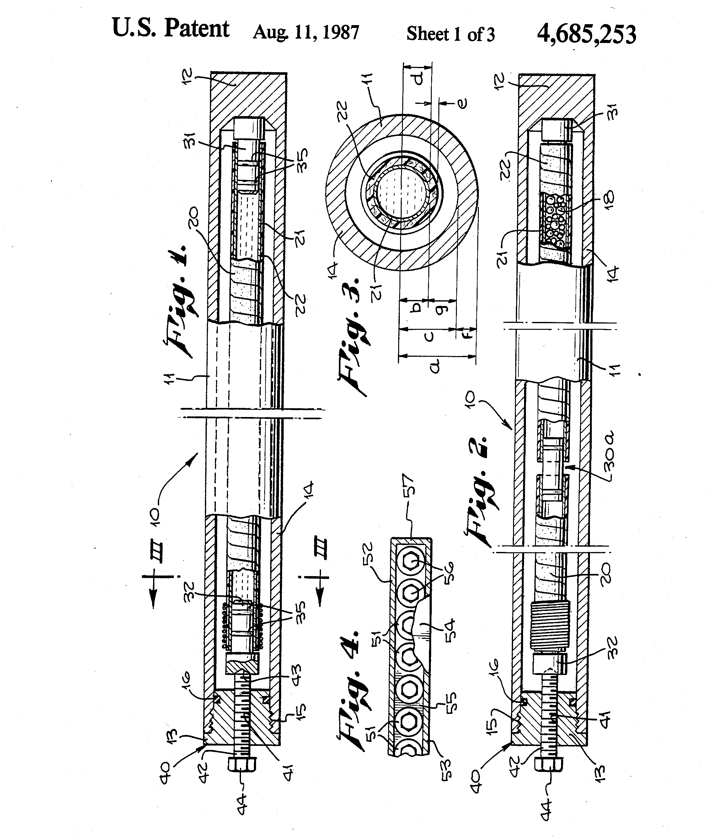
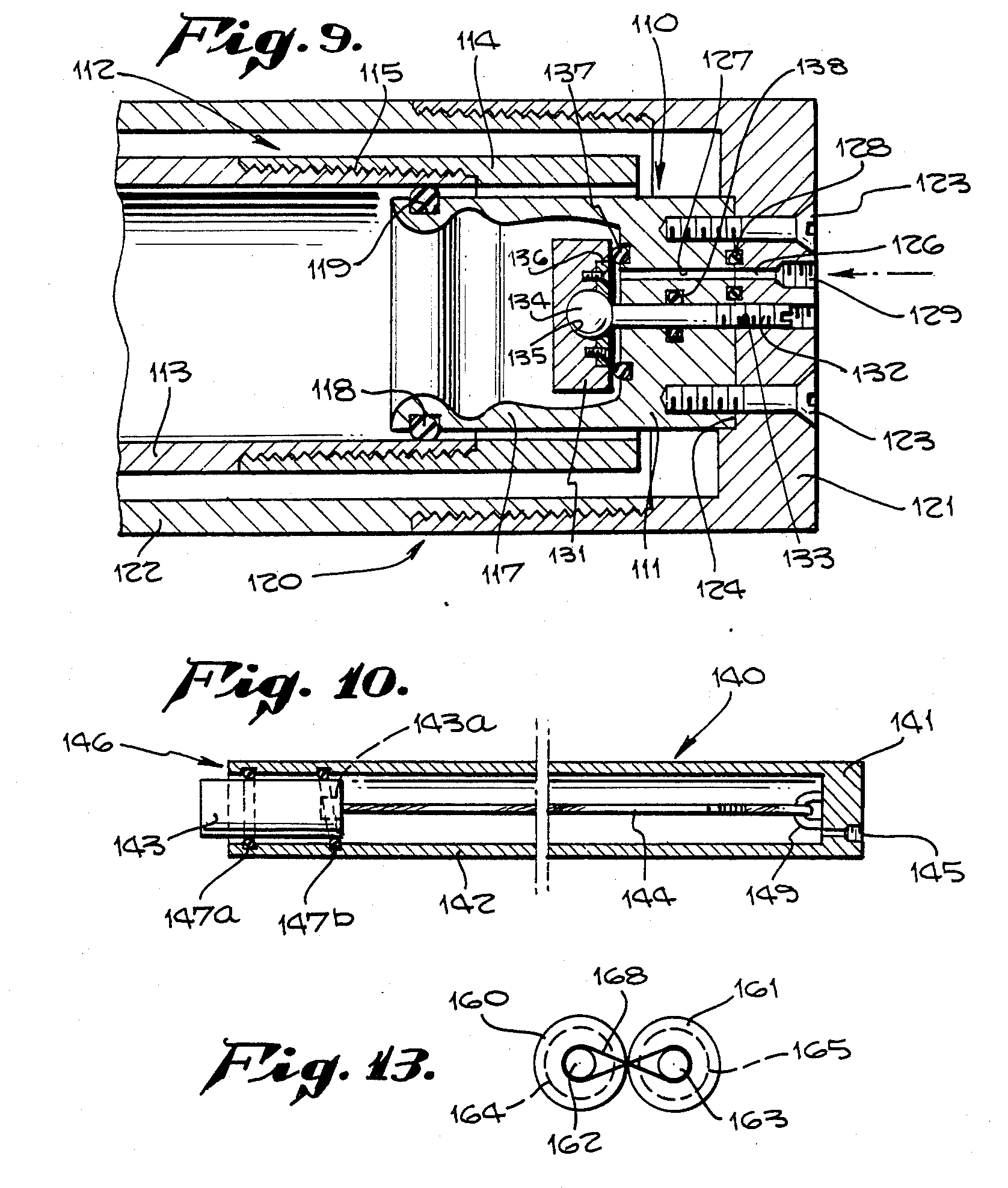
In Ostrovskii’s design, the binary liquid explosive is contained with a spherical shell, within this shell, liquid explosive consisting of benzene and nitrogen tetroxide is held under pressure. The spherical containment vessel is placed in front of a shaft connected to a series of fins that extend beyond the diameter of the sphere. As the capsule assembly is flushed through a constricting orifice, the fins are prevented from passing through and mechanically pull the diaphragm, allowing the explosives to mix. The time to fully mix the explosive compounds was estimated to be beyond 1.5 seconds. In Ostrovskii’s design, the energy needed to eject the capsules is provided by the flushing fluid. In alternative designs, the capsules might be designed as to be mechanically very stiff to permit it to be fired at moderate velocities from the nozzle, using compressed air, the ignition of flammables, an electromagnetic rail, etc to guarantee smooth detonation upon impact with the rock surface and or higher productivity by increasing the ejection frequency. 

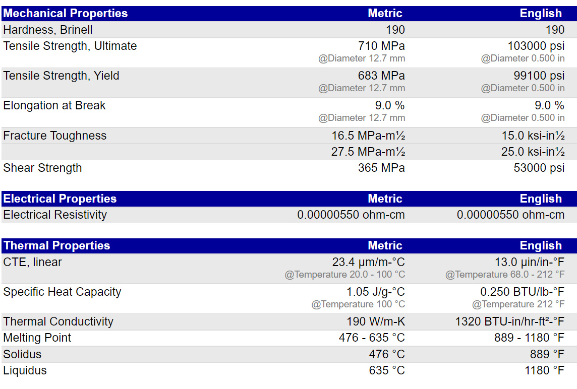
With conventional rotary bit drilling which relies on differential rates of abrasion between diamond and feldspar, drilling bits require a continuous feed of lubricating material, otherwise, the bits were down within mere minutes. Most drilling oils are hydrocarbon-based and cannot operate in such hot rock formations that occur at depths greater than 10 km. Most of the heavier hydrocarbons above methane decompose at temperatures of around 300 to 400 C. In contrast, explosive drilling requires no lubrication except for the internal mechanisms of the ejection nozzle which are sealed off from the surrounding media, thus, water can be used as optimal slurry media. The continuous flushing of cold water from the nozzle provides a sharp cooling of the capsule delivery hose and the nozzle maintains its temperature well below the temperature range of the explosive. It should also be remembered that since water has such heat capacity, the slurry never reaches anywhere close to the temperature of the rock since its continuously flushed and carries heat to the surface. Nevertheless, it’s critical to maintain adequately moderate temperatures to minimize the risk of thermal-induced detonation or damage to the capsules. The nozzle can be made of high-strength beryllium copper alloy such as Beryllium Copper C17200. Beryllium copper alloy such as C17200 is comprised of around 2.5% Berrylium, the alloy possesses astounding mechanical properties, boasting a tensile strength of over 1400 MPa and excellent all-around corrosion resistance, but especially stress corrosion cracking. Beryllium copper alloy is virtually immune to hydrogen embrittlement. The capsule delivery hose is insulated and constructed from braided nickel alloy or titanium hose. The capsules would likely be constructed from a metallic structural liner. The solid explosive, hexogen or cyclonite, is pressed to multi-hundred MPa achieving crystal densities in excess of 1.8 g/cm3. Since the explosive is already made very dense by compression, it cannot be compressed by the surrounding water media, so the capsule’s housing need only to provide adequate structural integrity but does not need to withstand the full hydrostatic pressure of the drilling fluid, which will be 120 MPa at the full depth of 12.5 km, or an average pressure of exactly half that. The insulation can consist of compressed argon gas to minimize differential pressure and compressive damage to the insulation. A porous solid media can then be used to prevent radiative heat transfer from the cold inlet water and the hot slurry passing along the hose as it’s pumped to the surface. To prevent damage to the nozzle head from residual shockwaves, the nozzle must be kept at a distance from the zone of detonation at the bottom of the hole, such as 1 meter above the bottom. Capsules are anticipated to maintain a level trajectory due to the straightening effect of the ejection barrel. Christophe de Rivals-Mazères Engineering, has developed a method where the explosive capsules remain isolated from the slurry media prior to ejection from the nozzle and are separably ejected from the energy of compressed air or diesel-oxygen combustion to allow for active modulation of their ejection rates. Ejection rates of up to 0.5 Hz allowing for drilling rates as high as 50 meters per hour can be realized if sufficient rock removal can be facilitated. Ejection rates are bottlenecked by the ability to remove fragments from the bottom of the hole, since there is no drill bit churning the rock fragments, they tend to accumulate at the bottom of the hole. Periodic stoppage and lowing of the freshwater ejection nozzle to just above the rock fragments will likely be necessary to provide the churning necessary to remove fragments.

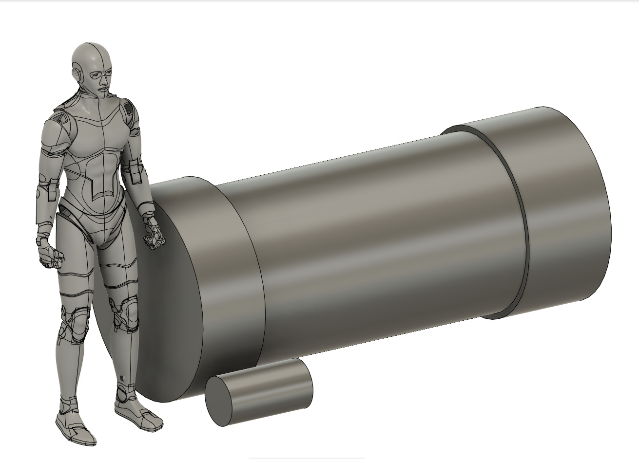
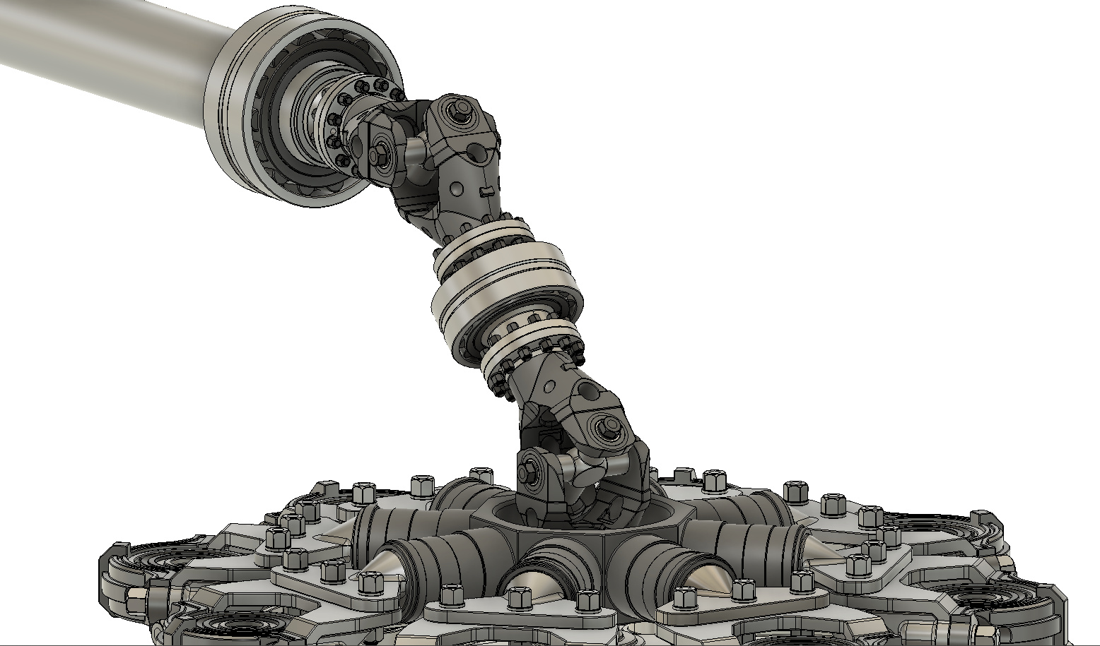
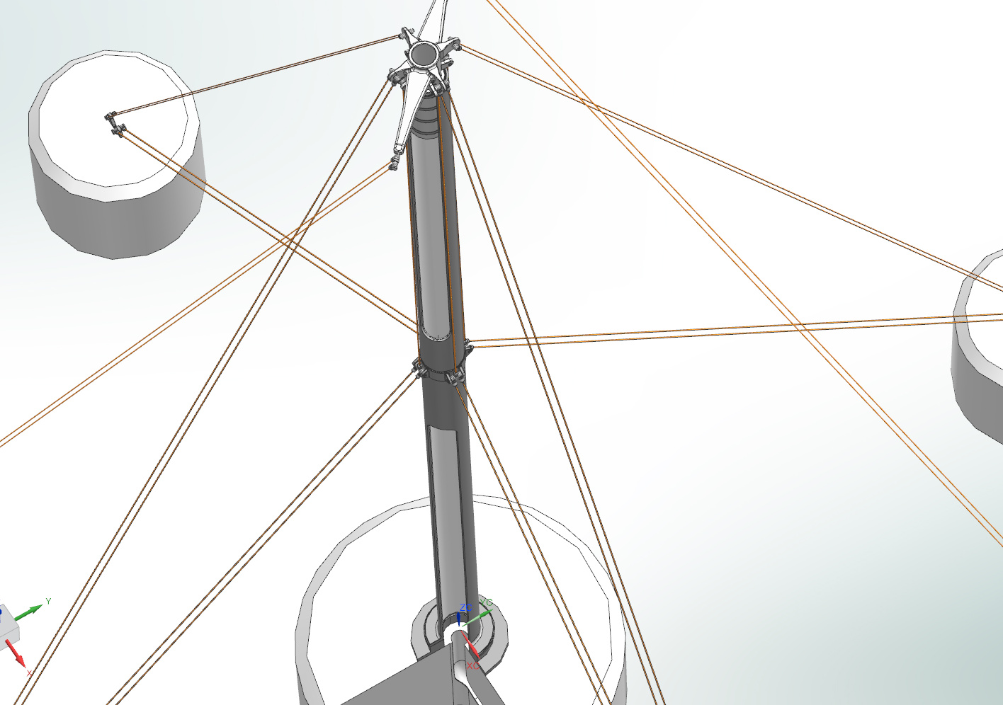
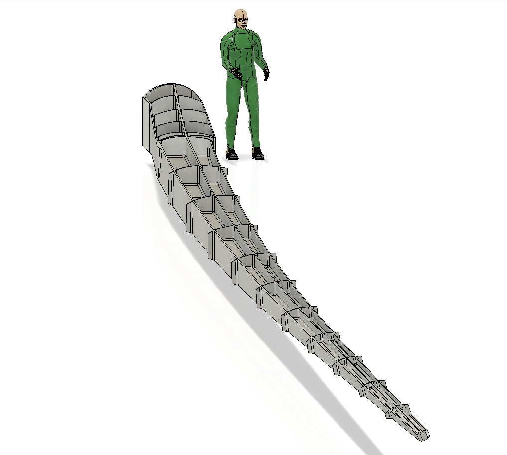
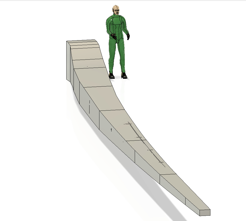
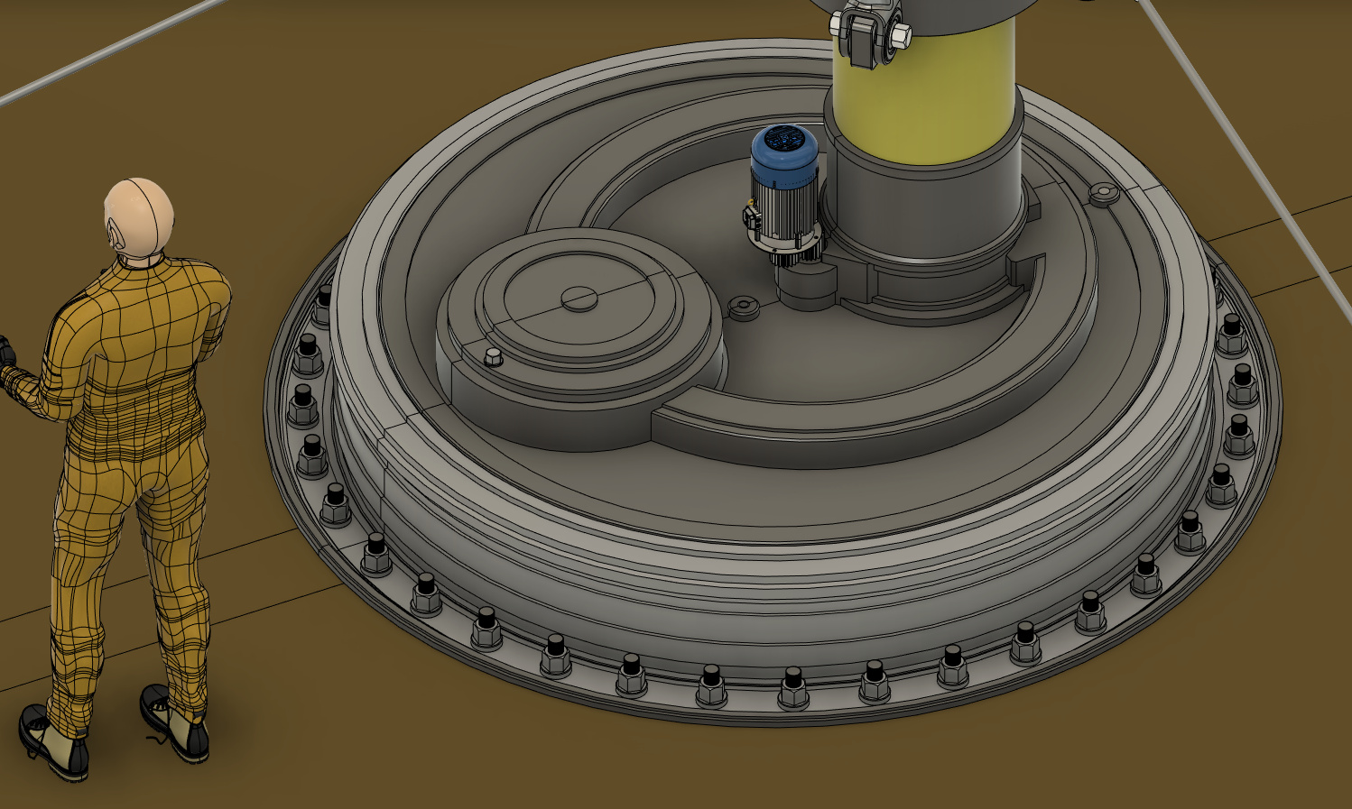
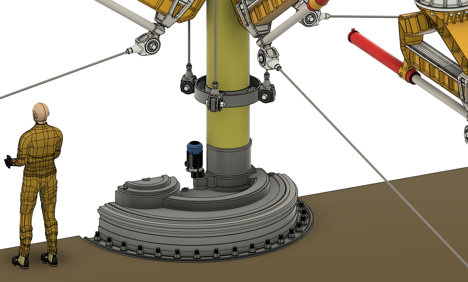
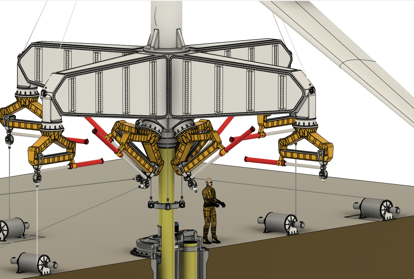
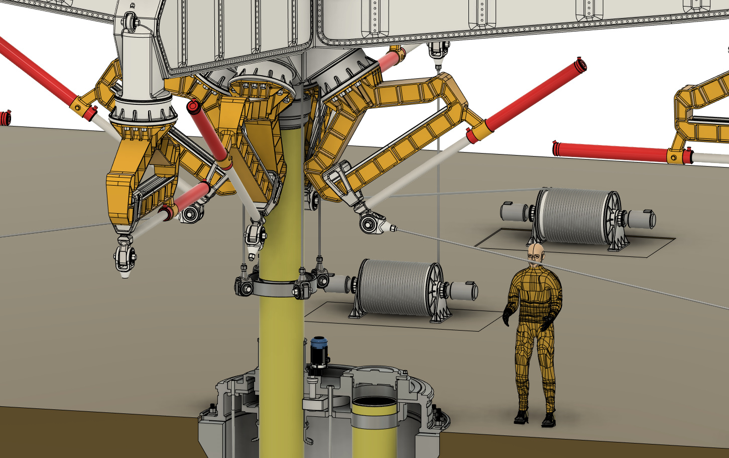
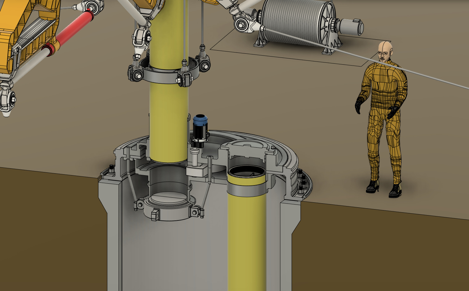
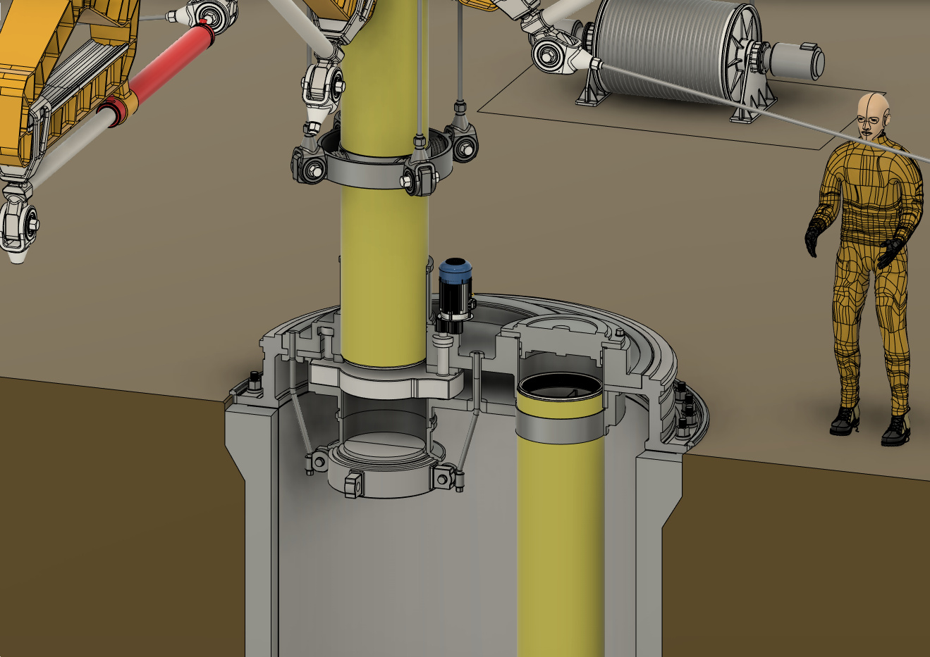
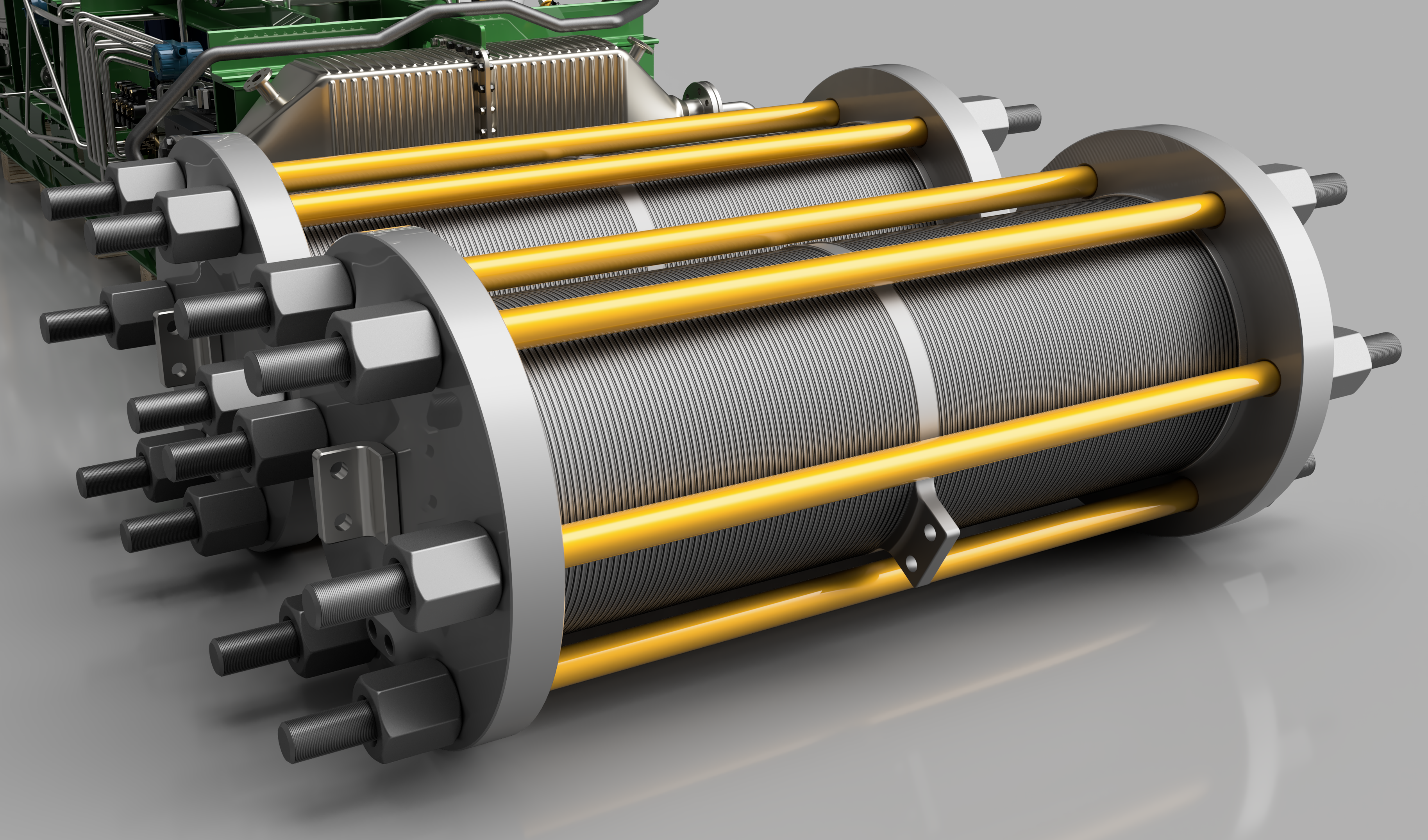
3D model and rendering of Christophe de Rivals-Mazères Engineering, proposed explosive capsule drilling module. The model above is suspending from a large diameter steel thin wall shaft. The steel shaft serves only as a pipe for facilitating the flow of cooling water to maintain explosive temperature at below its decomposition temperature. The large diameter shaft pictured above does not bear any loads but merely acts as a seal for the flow of cooling water which doubles as rock removal fluid. The inlet cooling tube is not a load-bearing member, rather, inside the tube, a series of metal-foil encapsulated aramid fiber load-bearing cables serve as the load-bearing members and carry the weight of the shaft assembly and the explosive capsules. The shaft section connects every 15 meters to a maraging steel fitting. Contrary to rotary drilling systems which require the shaft to transfer immense rotational force or torque, an explosive drilling nozzle generates only gravimetric force from its own mass and slight vibrational and recoil forces which can all be absorbed by the fiber aramid load-bearing cables. In contrast, the Hypervelocity drill requires a highly rigid shaft to absorb the intense recoil generated when firing the projectile at high velocity. The microwave drill is closer to ours in this respect, since it must bear only the weight of the waveguide.

Hydraulic fracturing will not work in plastic rock, meaning that no drilling beyond the brittle-ductile zone will ever be performed.

There is little point in drilling past 12 km or the brittle-ductile zone, whatever comes first. The main reason is quite simple. Unlike oil and gas extraction which can usually be performed by merely allowing the reservoir of the desired hydrocarbon to gush out into the drilled hole, a geothermal well requires a large heat exchange area. This heat exchange area must be artificially induced by mechanically fracturing the rock using a combination of pressure and thermal stress, combined with the chemical effect of water on the rock’s molecular structure. Once the ductile zone is reached, the rock now yields plastically making hydraulic fracturing impotent and ineffectual. The pressure of the rock would not serve to expand existing fissures but merely compress the rock and compel it to deform, but it would not lead to a root-like growth of tiny cracks and fissures allowing water to flow and pick heat. By definition, Hydrodraulic fracturing implies a “fracturable”, so one cannot expect any type of significant fracturing success in plastic, ductile, and elastic rock strata. Since there is little prospect of finding large amounts of oil and gas past this depth unless the abiogenic theory of oil and origins is correct, and geothermal fracturing is not possible, there is no commercial incentive to drill beyond the brittle zone leaving aside scientific or merely the sake of achieving such a technical milestone.

Novelty aspect #1: Viability of substituting the down-bore extendable nozzle with complete string lifting/dropping.

A minimum offset distance is required to protect the nozzle from the reflected blast pressure and prevent serious pitting of the metallic surface by high-velocity rock fragments. Pressure waves decay with the cube of distance in compressible mediums, so a maximum offset distance of at least 200mm has to be maintained. But in order for the evacuation of the fragments to be performed using a vacuum, the nozzle must be extended to physically touch or at least come very close to the fragment bed to perform suction. Any user of a vacuum cleaner can attest to its poor efficacy if the attachment is kept even a small distance from the surface. Of course, this to a large extent depends on the power of the vacuum, and the total pressure difference, but to minimize the size and power requirements of the suction device, it is desirable to minimize this gap. This creates an obligation to mechanically reciprocate a specially nozzle during each explosion cycle. It is conceivable that an alternative method where the entire drill string is lifted up and down in the well be developed, but such a method would require sliding the string along the series of packers expected to be installed during drilling. The actuation power needed to carry the multi-hundred-ton string would be very high and the speed at which it can be lifted will be limited. 

It is therefore expected that circumventing this design feature will be difficult and unattractive.

Novelty aspect #2: Viability of circumventing the suction spoil removal method

The use of air allows for explosive drilling to generate only small fragment size and the unique and highly novel option of using a negative pressure in the delivery hose to carry up fragments. The ability to circumvent this option is physically impossible, since the free-fall velocity of even the smallest is greater than the maximum speed of the gas traveling up the annular space between the drill string and wall. It is therefore impossible to remove the spoil through conventional aerodynamic means, hence requiring an internal spoil transport system. 

The proposed invention is to route the spoils once they have been picked up by the vacuum into a fluid-filled hose and then pump them to the surface using a medium-viscosity fluid. This option exploits the propitious explosive lending characteristics of gas while harnessing the efficient lifting capacity of high-viscosity liquid. The liquid spoil-carrying hose is fitted inside the main drill string housing and is provided with pumping power at the surface.

Novelty aspect #3: Viability of circumventing the capsule ejection angle adjustment method

In an explosive drill, regardless of the type of drilling media, the detonation of a charge will produce a spherical radius of fragmentation corresponding to the size of the charge. That is the radius of the explosion zone will remove a volume of rock in the shape of a somewhat compressed half-sphere. In order to drill holes in diameter that are larger than the maximum spherical radius, the ability to adjust the angle at which the capsules are ejected is desirable. This allows a smaller charge to produce a much bigger diameter opening reducing the pressure wave’s intensity and allowing a sizeable reduction in the offset distance of the nozzle. By installing a simple flexible fitting between the nozzle section and the main drill string, an adjustable azimuth capsule ejection barrel can be created. By rotating the nozzle relative to the drill string while the angle is kept in the same increment a pattern corresponding to the entire well diameter can be exploded. Angling the explosive charges also allows the drilling of variable diameter holes using the same size capsule.

One can envision bypassing this option due to the added convenience of having a fixed nozzle, reducing mechanical complexity, but the added performance, flexibility, and versatility the flexible nozzle affords make this an unattractive choice. There may be instances where a given mass of explosive produces a smaller hole diameter due to a harder, more plastic, or less porous rock, this means that the hole diameter is liable to suddenly shrink, potentially resulting in a situation where the hole diameter falls beneath the minimum threshold for the drill string to freely slide through the opening. Since the mass of the individual explosive charge is entirely fixed, and the frequency of explosive events alone cannot change the diameter since the least radius is constant, the only method to actively modulate the diameter of the hole is with the above method. AAI Corporation, working under a U.S Army contract to rapidly drill holes to place atomic land mines, attempted to get around this problem by employing a complex geometry with multiple shaped charges angled at 45 degrees from the Y coordinate. This design did not solve the issue of adjusting the wellbore radius since the shaped charges merely produced narrow indentations. 

Novelty aspect #4: use of pre-compressed gas.

While novel from a technical, engineering, and operational perspective, unfortunately, is not an active design feature or an invention, but merely something of a choice that is “known to those with skill in the art”.

Design exigencies of sequential capsulized explosive vertical boring technology.

Prior art by Ostrovskii, Robinson, AAI Corporation, among others, have alluded to the overall architecture or concept of fracturing or shattering rock in a controlled manner for deep bore-hole formation. Christophe de Rivals-Mazères Engineering,’s founder Christophe de Rivals-Mazères, revived the concept in 2022 after suddenly having the vision to use capsuled high explosives to shatter rocks rather than relying on the mechanical firing of projectiles. After a quick Google search, existing attempts were revealed, but since no major technical obstacle was presented, it made little sense that the concept was abandoned for fundamentally insurmountable problems. Considering our competition are attempting technically much more daunting concepts than mere explosive pellets being shot out of a tube, we believe it is worthy of reintroduction and final refinement and commercialization. The parties intending to commercialize this concept must now develop and refine the specialized mechanisms, methodologies, designs, as well as optimize the technical and operational parameters for successful application. It should be noted that while the concept can be simulated and conceptualized on a first principle basis, without extensive testing under the conditions, pressure, temperatures encountered, it will be difficult to anticipate all the variables which affect its design. A number of potential areas of intellectual property are listed hereinafter.

Flexible/rigid pipe assembly: High novelty potential: A method to deliver both slurry fluid, coolant, and the capsules/cartridges/charges must be optimized in order to accommodate the necessary insulation, load-bearing capacity (to suspend the mass of the nozzle and the entire pipe assembly), as well as provide for convenient insertion/removal ability and life adjustment of nozzle height. If materials allow, a hose may be designed to bend at a shallow radius to permit winding into a spool at the drilling set to reduce manpower requirements. Thin layers of bulk insulating material in an argon atmosphere can provide the necessary low thermal conductivity to mitigate the rapid heating of the capsule fluid. If insulation materials that provide this necessary flexibility are found to be impractical and or inferior to a solid configuration, straight 10-15 meter shaft sections are inserted into place and threaded in a similar fashion to conventional shaft drilling. The hose must be resistant to erosion by abrasion caused by small rock fragments traveling upwards at high speed in the slurry media. Another issue encountered may be cavitation damage to the hose as well as ejection nozzle due to small pockets of gas released when the explosive mixture is detonated. A throughout analysis and testing of both the nozzle as well as the shaft/hose’s durability will need to be performed to evaluate the degree of attrition engendered by a combination of shockwaves, gas pockets, rock fragments, and corrosive compounds present in the rock formation.

Explosive cartridge delivery: No novelty potential. A passageway in the main hose/shaft section in the diameter of the capsule plus a small additional margin to provide the needed flexibility to ensure no binding of the capsule and hose/shaft wall occurs due to thermal expansion. The capsule feeding section is placed in the inner portion of the main hose/shaft. Slurry and coolant delivery: No novelty potential. Cleaned distilled water is pumped at the necessary pressure to attain the desired flow rate through a series of separate flow passages surrounding the capsule delivery hose. A portion of this water is used for cooling the explosive and nozzle, flushing rock fragments, and providing ejection power for the capsules if compressed air is not desirable.

Active cooling of nozzle and delivery hose: High novelty potential: The ejection system must provide actively modulated ejection rates depending on rock hardness and rock diffusivity to minimize excessive comminution of rock media. Drilling speed is actively modulated with capsule ejection frequency. Capsule ejection: High novelty potential. Ejection power can be provided by either pressurized water or gas that is flowed in a separate hose from the slurry hose. A separate delivery line can provide the tailored flow rate for the ejection actuation energy that can be controlled via an electrical cable spanning the depth of the well. A method to prevent any clogging of rock fragments in the ejection barrel is critical, such a method may include a rotary valve and or maintaining water pressure above the ambient pressure to prevent any slurry from entering the capsule barrel.

Cartridge design and material: High novelty potential. Since the capsule housing material is recovered at the surface from the slurry separation system, high-cost lightweight and low-conducting materials can be used such as titanium to minimize weight on the delivery shaft/hose. The main cartridge structural liner is constructed just thick enough to prevent impact damage when the capsules encounter a rock fragment in the water. The liner does not need to be insulated since the residence time is so short. It is yet to be determined which material is ideal, field testing will determine the appropriate alloy/material. It is desirable for the capsule to be both somewhat aerodynamic and not too sharp to minimize the distance between the explosive and the rock bed. It is not expected that shaped charges will be used. It is important to select a capsule material that does adversely react with tetranitromethane.

The ability to rapidly remove fragmented rock is critical to avoid excessive comminution which serves to squander explosive productivity. This issue is especially pronounced with explosive drilling since there is no drill bit generating a constant “churning” force that imparts motion to the rock fragments. With explosive drilling, it is foreseen that the fragments will to a larger extent remain stagnant in the bottom of the hole. To counterpoise such a condition from occurring and retarding the drilling rate, the use of a heavily cased but relatively weak penetrating charge is used to periodically perform “heaving” action within the crushed rock bed to compel the individual rock fragments to migrate up into the slurry. This charge can be designed to penetrate the rock after a certain amount of fragmented rock piles up into the borehole bottom. This number would depend on the drilling rate and the effectiveness of water as a rock removal media. Since the explosive is a relatively small contributor to the overall cost of the system, the use of high drilling speeds at the expense of high rock comminution and explosive consumption can be considered. But the issue is not merely a matter of explosive consumption, when excessive amounts of rock fragments build up in the bottom of the wellhole the subsequent charges have very little potency in removing further rock, so productivity slows drastically. Therefore, even if penetration speed is increased, there is an inventible clearly defined limit imposed by the divergence between slurry removal efficiency and fragment buildup. The penetrating heaving charge is theorized to bridge this gap and augment drilling productivity. Its purpose is to remove small layers of rock fragments that build up and become compacted by the subsequent primary fracturing charges. Some may wonder what possible difference could exist between a small penetrating charge and the major fracturing charges. The difference is that the primary charges are much more powerful, but since they do not penetrate any significant depth, they generate a powerful shockwave pushing down on the rock bed, rather than heaving them, they compact them and push the rocks towards the side. The penetrating charge is just strong enough to generate a gas volume to impart considerable churning and heaving motion to the rock fragments, without further comminuting them. Since the charge penetrates a greater depth than the primary charge, the explosive takes place inside the fragmented rock layer laterally pushing the rock fragments against the wall and upwards. The upward motion of the individual fragments allows the liquid opportunity to pull them up into the borehole.

Choice of explosive: No novelty potential. Short of discovering a new molecule, the designer is limited to the available explosive compounds. Liquid explosives entail too much hassle, with elaborate failure prone mixing diaphragms, extreme sensitivity once mixed, and low decomposition temperatures, render liquid explosives no safer than solids. The ability to melt-cast cyclonite Hexanitrostilbene was successfully used on the Apollo program for generating shock waves for experimental seismic sampling and for actuating the landing gear. It was chosen due to its excellent performance in high vacuums for an extended time. Hexanitrostilbene is not inherently a high-cost explosive as for example HMX, since it can be readily synthesized from trinitrotoluene, a low-cost explosive. A solid explosive is ideal due to its added simplicity since it eliminates the mechanisms imposed by the need for mixing. Liquid explosives also confer added leakage risk which may go unnoticed in the nozzle and delivery pipe at the great depths operated. Leakage can potentially cause a sudden detonation if leakage occurs from both the oxidizer and fuel sections of the capsule and are allowed to mix in the ejection barrel and delivery hose. In comparison, a solid explosive can be easily sealed and prevented from dispersing into the environment. A potential disadvantage of solid explosives is their pressure tolerance, very little data exists on solid explosives at very high pressure, while for liquid explosives such as TNM/Toluene, considerable data is available suggesting continued stability and detonability at pressures as high as 4000 atm. Hydrostatic pressures at 15-20 kilometers will be between 2000 and 3000 atm. Due to the more complicated manufacturing process for solid explosives, liquid explosives are a more economical option, but do not seem ideal other than their added safety. The explosive must be manufacturable at scale in order to facilitate large-scale deployment of the technology. Tetranitromethane has a boiling point of 130°C, and while its exact decomposition temperature is not known, is expected to begin rapidly decomposing at temperatures in excess of 300°C, although no data is available. Toluene begins to very slowly decompose at 350°C. An overlooked opportunity is the potential to extract useful work from the compression of explosive oxidization gases. The gases generated during the oxidation of the explosives are immediately compressed by the surrounding water media generating a high-pressure gas that can be used to extract useful work, potentially covering a portion of the slurry pumping energy. This may emerge as an interesting opportunity for novelty. The need to minimize cavitation of the shaft and nozzle by the flowing high-pressure gas bubbles is also projected to form a crucial design exigency.

Height ascertainment system: Medium novelty potential: Height from the wellbore bottom can be ascertained each time device is descended periodically to maximum flushing. Alternative methods include low-frequency sound waves which can penetrate through dense water using time of flight to infer distance. Another method is to simply measure the shockwave propagation time, a high-fidelity pressure sensor can be installed on the nozzle tip to measure the time it takes for a shockwave to propagate from the point of capsule ejection which is a known starting point.

Shockwave absorption system: High novelty potential: Since explosions generate supersonic shockwaves that travel upward in the liquid media, if the nozzle is placed too close, cracking of the metal can occur. The nozzle is thus designed with a conical shape to blunt the shockwaves using the same principle as an MRAP military vehicle which uses a v-shaped hull. Since the overpressure of the shockwaves declines rapidly with distance, keeping the nozzle at only a slight distance, such as 100mm above the explosion zone, can successfully keep cracking risk to a minimum. Unfortunately, as well size increases, the distance must increase as well since each explosive charge grows in power. This imposes an unacceptable loss in fragmentary removal efficacy since the zone of water discharges is moved a further distance away from the rock fragment bed. Such a condition compels the designer to search for an option to place the nozzle as close to the detonation as possible. But in doing so, a number of design exigencies arise. When the shock waves strike even the conical body, they impart sharp energy which can induce fracturing of the metal. This may require both a shock attenuation system using springs or compressible gas to serve as a shock absorber to blunt the shockwave energy from placing excessive strain on both the conical nozzle and the suspension shaft (if a hose is used this is not an issue since it will simply bend). But it is not certain that such a shock-wave attenuation system would necessarily prevent cracking of the nozzle head since the shockwave still strikes the metal surface, and at such an elevated velocity, the recoil time is far too latent to cancel the force imparted upon it by the shockwave. Another option that may be suitable is a compressible layer that can be lined on the surface of the metallic nozzle, much like an ablative phenolic resin coating used on MIRVs. Except that rather than a thermal effect as in the MIRV, the coating serves to absorb as much of the shockwave’s energy in slowly compressing and cracking the material as to attenuate the net force transferred to the metal beneath it. This liner of a yet-to-be-determined material can be periodically replaced. Regardless of the mechanisms used, it is expected that nozzles will have to be replaced periodically due to gradual crack evolution and fatigue cycle accumulation in the metal tip from local stress concentrations from the overpressure. Since the hydrostatic pressure places a 200+ MPa continuous compressive load on the metal, the metal nozzle and any metal components are already at continuous loading conditions which reduces their fatigue life perceptively, especially at the elevated temperatures they operate under. If this crack growth is allowed to persist, catastrophic failure can occur. It is, therefore, necessary for a design that can accommodate easy replacement of the nozzle section to be implemented.

Detonation and initiation mechanism: High novelty potential. There is little to no civilian experience using explosives in high hydrostatic pressure environments. Only naval landmine technology, military underwater explosive placement for demolition, etc utilizes explosives in a high-pressure water environment. The detonation mechanism must not only accommodate the effective mixing of the mixtures and timely detonation, but also the reduction in sensitivity due to hydrostatic pressure. Since water has a density of 798 kg/m3 at 250°C(which corresponds to mean well temp) the hydrostatic pressure gradient will be 8 MPa/km or 117 MPa at 15 km. There is a great need to develop specialized and tailored detonators for these demanding environments. An optimal ignition system is the magnetic activation of a piezo-electric plunger to initiate a primary non-pressurized binary mixture to cancel the desensitization with pressure. This initial ambient pressure but highly sensitive mixture is then placed inside the “mother” cartridge to set off the main secondary but less sensitive explosive. This detonator charge is prevented from being compressed by the surrounding primary explosive with a small metal or composite pressure vessel. This represents a significant departure from Ostrovskii’s prior art of using impact detonation, since greater depths will cause high excessive desensitization which may make it difficult and or unreliable to rely on such a detonation strategy. Alternative but less proven methods may include using powerful electric charges to detonate the primary explosive, sudden heat, or simply increasing the impact energy of the plunger. The least desirable but potentially necessary solution is to simply carry onboard separate small detonator charges made of a high-temperature but solid explosive in pressure-restraining vessels to be inserted into the capsules prior to firing and or kept on board the capsules. But such an option would seem to negate the purpose of the binary explosive in the first place. The last and likely unattractive option is encasing each primary liquid explosive charge in a pressure-restraining or partially pressure-restraining casing to minimize desensitization. This will entail much heavier capsules and a portion of the energy of the explosive used to burst the metal, so it is desirable to search for solutions that can allow the primary explosive to be maintained at the surrounding media pressure.

Capsule manufacturing: High novelty potential. A method for the low-cost mass production of capsules, their safe filling with explosives, and their transportation. Due to the inconvenience of safely filling capsules on site, it is more desirable to transport them by truck to the drilling site in their prefabricated form. A number of design details will need to be highlighted to ensure safe transportation on civilian roadways. If this risk is deemed too great, capsules can be filled by separate liquid tankers at the drilling site using a containerized factory.

Blowout prevention:  Very high novelty potential. Regardless of whether liquid or solids are used, accidental detonation must be assumed to occur at a specific occurrence which is a direct function of the probability of exogenous shocks and or endogenous failures occurring in the system of the rock media. If the experience results in a hypothetical failure probability of one in 100,000 hours, a necessary method must be in place to minimize catastrophic damage to surrounding surface ancillary equipment and nearby persons. Causes of accidental detonation may emanate from extraneous phenomena such as well cave-in caused by a sudden loss of fluid and pressure, the blockage and accumulation of rock fragments in the area between the hose and well wall, erosion of the delivery hose, seismic perturbations, embrittlement of metal components, cracking of capsule housing, failure of the diaphragm separator, failure of mixing system, failure of the cooling channel to maintain the explosive temperature within safe limits, failure of detonator, failure or blockage of the nozzle due to debris clogging, violet recoil caused by an accumulation of cartridges in the wellbore (multiple undetonated capsules detonating at once), failure of distance measurement system causing the nozzle to be too close to detonation zone causing severe of the nozzle by shockwaves, among many other not yet to be anticipated causes. It is therefore an exigency of the highest order that an effective mechanism to shield workers and equipment from the blast shockwaves traveling upwards is designed. Such a “shockwave attenuator” device is essential and cannot be obviated and hence may form a key component of the intellectual property. The blowout prevention system should really be named a shockwave attenuation or absorption system. When oil and gas are extracted from the crust, the release of large volumes of substance can exert forces on the well cap that exceeds its restraining strength, causing a catastrophic release of oil or gas into the environment and potentially harming workers. With geothermal drilling, rock geology tends to be harder, less porous, that is metaphoric, and igneous, rather than sedimentary, leaving little opportunity for the release of pressurized substances. The reason that oil and gas drilling, but especially horizontal drilling, can induce artificially seismicity, is due to the removal of large volumes within the crust, causing a natural reactive movement within the rock bodies. With detonation drilling, an entirely new set of exigencies exist which still serve to generate consternation with respect to the sudden release of pressure. The blowout prevention system would in effect be a large valve that instantly shuts off the flow of water out of the well. Since the detonation of some or all of the capsules would generate an immense shockwave, the blowout device must be designed to withstand pressures considerably in excess of those encountered in conventional oil and gas drilling. Another unique feature is that, unlike oil and gas drilling where the blowout prevention device is inserted after the drilling is completed, with the explosive drill, the device must be active during the entire drilling process. This is because we are not trying to prevent the escape of the well’s containments, but rather the stochastic and unpredictable capsule detonation event. The blowout unit is therefore highly unique since it must accommodate the large shaft as it passes through the opening. Nothing like this exists in the oil and gas drilling industry and hence endows a great deal of novelty upon the designer. In order to facilitate the sliding of the shaft while simultaneously providing blowout blockage, a system where the weight of the suspended shaft is used to cause the entire assembly to drop just below or horizontally or angled plunger shaft which closes the flow upon the drop of the drill. But the shrewd engineer should not rely on secondary measures to mitigate catastrophe, he must rather rely as much as possible on primary preventive measures. Such measures include making it almost impossible for individual capsules to spontaneously encounter conditions where detonation energy can be provided by natural circumstances, namely shocks, impacts, or diaphragm failures. This will be achieved with scrupulous attention to capsule quality. But nevertheless, a capsule containing a manufacturing flaw mat inevitably enters the supply, to absolutely eradicate the menacing risk of a chain detonation, a novel system where the capsules are protected with a “buffer zone” of fluid is adopted and chronicled in further detail. Since the explosive capsules are stacked vertically in the delivery hose, the cumulative explosive charge is the sum of all the individual cartridges, which represents a potential explosive power of tens of tons of TNT or more. The bulk of this energy would go to generating micro fissures in the rock since there is nowhere for the water to escape since the blowout prevention module is simply too strong to permit it to escape. Since the operator is compelled to minimize the event where all of the capsules detonate in a chain reaction, where the detonation of one provides the activation energy for another, a method to vertically separate the individual capsules is called for. Such a method may simply utilize a vertical column of water or more ideally, compressed gas, to provide a buffer zone to absorb the explosive power of a single capsule and prevent its spread to the adjacent one. The explosion of a single capsule would result in the destruction of the delivery hose, but if the explosive power is sufficiently absorbed, this force would no doubt destroy much of the shaft and hose assembly, but it would not detonate the rest of the distance capsules. In order to maintain this vertical gas or liquid column, each capsule is fitted with a seal that slides firmly against the tube wall. This makes it impossible for the capsules to fall atop each other since the media in between them would have to be compressed.

High flow cooling allows for PETN or RDX to be used with similar detonation velocity to cyclonite as well as the use of aluminum conductors to power down bore hydraulic pump. It cannot be overstated how advantageous a lower operating temperature is to the overall system’s reliability and safety. Since all ferrous and non-ferrous alloys lose strength with increased operating temperature, cooling increases the structural efficiency of the mechanism, reducing weight and thereby increasing retraction speed. An array of sensors and data collection is essential for adaptive operation, such as adjusting capsule ejection rates depending on rock hardness or the desire to achieve optimal particle size with comminution using additional explosives. 

Cooling is the sine qua none of any advanced drilling technology. A number of components, sensors, and structural materials must be maintained at moderate operating temperatures to maintain their strength, stability, and performance. Explosive drilling is no different. But it may come as a surprise to some that in fact, the explosive chemical itself is not the limiting factor in the thermal management of the system. Electronics, notably the solenoid mechanism, pressure, thermocouples, data collection unit, and delivery cable are what limit the temperature of the system. Thankfully, physics and chemistry work in our favor. Water happens to have the highest heat capacity of any substance besides hydrogen, helium, lithium, and ammonia, a relatively small flow of cooled water can more than satisfactorily remove all the heat produced by the rock. Using only 200 bar of pumping pressure, in the 350mm delivery hose, a flow rate of 2100 cubic meters of water can be delivered to the drilling nozzle and back along a 12.5 km distance. A 200-bar triplex pump requires only 6 kWh/m3, such a highly cooled drilling apparatus would draw 12,600 kW of power. If the well is drilled over a 2500-hour period, corresponding to a speed of 5 meters per hour, the cost at 7 cents per kWh is around $2,200,000. But this number is far too high. The realistic sustainable operating temperature of the system is around 100 degrees C, well within the operational limit of high-temperature silicone carbide electronics and many sensors, and will be within the operational limits of cyclonite. Since the average surrounding rock temperature is 218.75 C, 35 C/km x 12.5/2, then we need only to lower the temperature by 118 C. If we choose to be more aggressive, we may settle at a temperature difference of 2.5 or 3 times, bringing out drilling unit temperature down to 70 degrees we must lower the well temperature by 148 degrees. The question is then how much water must we pump to achieve this? We first need to estimate the heat penetration rate, using this calculation, we arrive at an average thermal energy production over 2500 hours of just under 30,000 kWh. The rock is not a source of infinite heat, if more heat is drawn than it can produce, it will cool, but this is not our objective, our objective is to pull just enough heat so that the average temperature of the water does not reach an equilibrium with the rock wall. Since water has very low thermal conductivity, such a large diameter well will have a difficult time heating the block of water inside it, resulting in the rapidly flowing water possessing a lower temperature than its surroundings. Since the average temperature of the water is 70°Cand at 700 bar its density is 1007 kg/m3, the specific isochor heat capacity: cv is 3.795 J/kg-K, the volume needed is only 192 cubic meters, or ten times less than we can pump at 200 bar. This means we only need around 250 kW of power for the pumping machine, bringing out power costs down to only $45,000 per well drilled. Since we need more than 200 cubic meters for spoil removal, if we assume that the drilling fluid should not possess a fragment concentration of over 1.5%, then if we excavate 5 linear meters of rock at a diameter of 550 mm, we produce 1.15 cubic meters of rock per hour. We therefore need only 75 cubic meters per hour of drilling fluid. Of course, this number must be higher since a minimum velocity of 5 meters per second is desirable to remove heavier particles. If the flow rate is set at 800 cubic meters per hour at a pressure drop of around 230 bar, the power is 5600 kW. 

Explosive drilling can more easily bore large diameter holes than rotary drilling, there is much more area available for both coolant and slurry flow. Since pressure drop is a function of viscosity and the total surface exposed to the flow, larger diameter tubes will permit higher flow rates. The Explosive Drilling Systems Inc mega-bore

If one performs basic pressure drop and flow calculations for gaseous drilling media, it becomes immediately clear that any drilling technology which is unable to use water or oil is basically impossible. Gases are compressible which means they incur much more turbulent flow and possess intrinsically much more viscosity. The results of this analysis s based on a reputable UK software program. The calculations show that it is effectively impossible to circulate enough nitrogen gas (used in the analysis) to remove the spoils not to mention the even more important requirement of cooling the wellbore. Unlike liquids, gases become more viscous as temperature increases, this is on top of nitrogen’s already 86-fold higher viscosity than water at 200 C. With a hypothetical flow diameter of 200 mm and a length of 38,000 meters (equating to a complete flow along a 15000-meter depth plus additional length to represent the added surface area of the annular flow path), the available flow rate for nitrogen compressed to 100 bar is barely 75 cubic meters per hour. Since the density of nitrogen at 100 bar is 120 kg/m3, only 800 kWh of heat can be removed with a temperature rise of 300 C. This is many orders of magnitudes below the requirement to lower bore temperature by many hundreds of degrees at the 10+ km depths where wall temperatures in excess of 400°Care encountered. It is also far less than what is needed to absorb heat produced from the hot vapor as it passes along the waveguide, not to mention removing heat from the waveguide from losses. The conclusion is due to the physics of compressibility, only liquid can be used for cooling. most of the pressure drop is not caused by viscosity, but by the turbulent flow enabled by compressibility.

With explosive drilling, when one performs a fundamental technical analysis by scrutinizing all the disparate parameters, one will quickly discover that there are no fundamental technical constraints. As long as the system is maintained at temperatures, we have a wide array of explosive options and the ability to incorporate sensitive electronics which will prove critical for adaptive operations. But most importantly, the combination of a very high slurry flow velocity facilitated low surface-to-volume large diameter bores, moderate to high viscosity water base fluid, and a reciprocating nozzle that provides intense churning force directly above a highly comminuted rock bed, we should be able to extract spoils much more effectively than Ostrovskii did or as effectively as rotary bits can.

The most frightening thing for an engineer is an insurmountable technical barrier that stubbornly refuses all attempts at amelioration. With this system, there doesn’t seem to be any one phenomenon that isn’t receptive to at least partial solutions which can be accepted by making trade-offs but still retains the underlying workings of the system.

It shouldn’t come as a surprise that the only truly “alternative” drilling technology that has indeed been tried is none other than this one out of all the possibilities mentioned in that book. This should serve as an endorsement of the underlying simplicity of the method.

The heat of detonation of most explosives is about 4-5 MJ/kg, or about 12.46 kWh/kg. Since explosive productivity of 50 kg/m3 of rock volume without comminution and 100-150 kg/m3 of rock with comminution is expected, the amount of heat released by an explosive drill with a drilling rate of 5 meters per hour is 1380 kWh, which is a negligible number. Compression heating of the water is negligible since water is largely incompressible with a bulk modulus of 3.5 Gpa.

The over-pressurized air drilling revolution

Prior concerns about air drilling mainly focus on the inherent inability of gaseous mediums to prevent the influx of liquids into the wellbore. It has apparently not been considered that gas can simply be pressurized above the formation pressure, even less than a few bars above it, is sufficient to completely halt the influx of unwanted liquids. Freshwater experiences a hydrostatic gradient of 10 MPa/km, but the real number is slightly less since the water will reach the temperature of the rock and its density will drop slightly. There is no technical limitation present with requiring the gaseous drilling media to be pre-pressurized close to the highest formation pressure likely to be encountered in the well. For example, if we use nitrogen compressed to 700 bar at 50 C, it will have a density of 463 kg/m3. Subject to a gravitational pressure gradient equal to 12 km, its pressure will rise by 545 bar. Thus, the gaseous drilling fluid will now have a hydrostatic pressure of 1245 bar, just above that of water with a density of 950 kg/m3. The equipment necessary to contain this high-pressure gas is commercially available or can be readily engineered for this application. Liquid piston ionic liquid compressors can be employed with very high efficiency. 

Explosive drillings almost entirely depart from the fundamental assumptions encountered with rotary drilling in oil and gas applications, hence the drilling media, one of the most important variables, is also expected to change.

When explosives are set off in a compressible atmosphere, the preponderance of the shockwave energy is deflected upwards away from the hard surface and its energy is absorbed by compression of the gas molecules. During an explosion in liquid, the shockwave decays at a much slower rate, a difference of around 100 times. This incompressible block of mass contains the shockwave and forces more of it to pierce through the rock, but rather than crushing it into small fragments, it spalls it into much larger fragments since more energy is directed towards disintegration or spalling, but not crushing. This is understandable, since the yield of rock removed by explosive is over 10 times greater in water, necessarily, less energy is directed towards comminution and more of it towards piecing and blasting the rock into larger shards. With underwater explosions, a jet of highly compressed water acts almost like a mechanical cutter, breaking through the rock. With water, the average fragment size was slightly over 20mm, while in air, most of the fragments were powder sized, 500 microns. With liquid drilling, some fragments as large as 40mm were produced. Using the Fergusen and Church equation for particle settling velocity, a 40mm particle will fall at a rate higher than the practically attainable fluid velocity even with very high viscosity, resulting in an accumulation of these fragments in the rock bed. Unless these fragments are effectively comminuted back down to no more than 15mm by subsequent explosions, liquid explosive drilling may not be feasible.

It is expected that the mean fragment size will moderately increase with gas density, but not markedly, since compressibility drops to 0.234 kg/3/bar at 1000 atm down from 1.15 kg/m3/bar at 1 atm. Since water is 10,630 times less compressible than air, water having a bulk modulus of 2.1 GPa experiences a -0.00004762 m3/bar at a starting pressure of 1 atm. Since the difference in compressibility is 10,600 but the difference in shockwave propagation is only 100-fold, we can expect only mild changes in behavior under high pressure but compressible atmosphere. 

Quoting Ostrosvkii in “deep hole drilling with explosives”:

“After several explosions in air a funnel 60-70 mm deep and 300-350 mm in diameter at the top was formed on the surface of granite. During the subsequent penetration, the surface was not shattered and a hole of true cylindrical form was developed, 80-90 mm in diameter (as against 300-350 mm for underwater explosions). The average penetration per explosion in granite was 16 mm in a hole with no water. In producing this hole the size distribution of crushed materials differed from the distribution in water-filled holes (formed by explosions) in the predominance of strongly comminuted particles; the following table shows the distribution: 

Quantity of granite detached by detonation of a single charge (40 grams): 0.22 kg. Content of particles (in %) of size (in mm): greater than 7 mm 7%, from 5 to 7 mm 2%, from 3 to 5 mm 9%, 0.5 to 3 mm 20%, smaller than 0.5mm 62%. The particles of granite extracted after an explosion were crossed by numerous fractures; they consisted of clumps of crushed crystals. Structurally, altered crusts of granite, predominant features of underwater explosions when sinking holes by explosions, were not observed after explosions in air”.

The consequences of this highly comminuted fragmentation characteristic in air media are immense for deep drilling. Spoil removal had plagued Ostrovskii’s system due to the high freefall velocity of the heavier 40mm fragments, severely hampering drilling speeds as fragments piled in the well-bore floor serving to blunt the subsequent explosions. With air drilling, the small fragments can be very effectively evacuated from the bottom of the wellbore by using a down-bore suction pump. A vacuum of only a fraction of an atmosphere is enough to lift heavy pieces of gravel along multiple meters of hose. Vacuum removal of rock, soil, sand, and grain is widely used in industry. A method called “hydro-excavation” employs powerful vacuum pumps to suck dirt out of holes stimulated by water jets. The suction pump can be a liquid vane pump, positive displacement, a dry impeller, or even an ejector (Bernoulli or Venturi nozzle). When the fragments are brought inside the spoil containment unit between the suction pump filter and the inlet, they are continuously fed into a closed-loop liquid-emulsion hose where a moderately viscous liquid carries them to the surface. Since the fragments are small in diameter, they are readily carried to the surface with moderate pumping powers. In this configuration, the suction pumps only serve to elevate the fragments a few meters into the vacuum filter chamber, the rest of the carriage is performed by the pumped liquid in a closed-hose assembly within the main drilling hose. With this novel over-pressure dry drilling technology, pumping power is reduced and the only liquid in the system is isolated within the drilling nozzle. 

It’s interesting that the difference in compressibility between air and water is 10,000 times. If a 1 kg TNT charge is detonated at a distance of 5 meters, the overpressure in water is around 140 bar, while in air it’s only 1 bar. While in a denser compressed air gas atmosphere, one would expect the pressure decay to occur somewhat slower, the difference will likely not be large since air remains almost as compressible at the equivalent hydrostatic pressure of water as 12 km. If we extrapolate the pressure wave decay rater as a linear fraction of the compressibility, we can estimate the additional shockwave pressure, then if the compressibility factor of water is 10,000 and air is 1, and the shockwave wave decay rate is 100 fold difference, we can simply divide the shockwave pressure decay ratio by the compressibility ratio and then multiply by the decrease in compressibility, arriving at an increase of only 0.08 times the distance traveled in a 1000 bar gas atmosphere. Of course, there is no empirical formulae available from the literature nor any experimental data on explosive shockwave behavior in high-pressure gas atmospheres, so we can only deduce a relative ratio assuming linearity, but this may not be the case, but observing the differences between the two extremes, nearly no compressibility, and almost infinite compressibility, it’s not expected a small 8 fold drop in compressibility would substantially alter both the shockwave distance and the comminution behavior. Although it must be tested before financial performance can be calculated with any degree of confidence. But what can be said is that a 1000-order-of-magnitude decrease in compressibility only increases the shockwave pressure by 10 orders of magnitude. 

Oil and gas drilling occurs in highly porous, soft, plastic sedimentary deposits with large adjacent reservoirs of liquids under great pressure. This forces oil drillers to use high-gravity weighting agents such as barite to increase the hydrostatic pressure of the drilling fluid to above the formation pressure. In geothermal drilling, with the use of modern prospecting technologies or what’s called “exploration geophysics”, including technologies such as magnetotellurics, transient electromagnetics, rock strata with low water and hydrocarbon content can be identified permitting dry drilling. In cases where groundwater is still present, an over-pressurized drilling strategy is employed, but this strategy can still use gas. 

In rock strata that are largely dry and structurally intact, the use of an underpressurized drilling regime with gas enables greater depths due to negating the pressure-dependent desensitization of the explosive. Ultimately, drilling depth is limited by the brittle-plastic transition zone, which can occur as shallow as 10 km to as deep as 20 km depending on the intensity of the geothermal gradient and rock type. Granitic rocks have a high threshold for plasticity, as high as 800 C, while quartz can be as low as 350 C. When the rock becomes excessively plastic, much of the explosive energy is diverted to compressing the rock, and drilling productivity is expected to fall off sharply. Moreover, wellbore stability will be severely compromised and collapse will ensue. This suggests an upper limit of about 12 km, corresponding to around 400 C down bore temperature, is the limit regardless of drilling technology. the real untold limit to drilling depth is neither technology or heat, it’s the brittle-ductile transition zone that depending on the age of the strata, occurs around 15 km where rocks lose much of their brittle nature and will yield plastically, making well-bore collapse almost inevitable, not to mention rendering explosives useless.

#1 The ability to increase drilling rates between 10-50x fold over liquid due to small fragment size eliminates the issue of well-bore cleaning. Productivity depends on vacuum power and powder removal speed more than explosive delivery rate. 50 m/hr is more than feasible.

#3 The rapid attenuation of blast incident pressure due to gas compressibility allows a higher frequency of capsule delivery without transmission of initiation pressure without the use of a valve of capsule delivery and reduced need for nozzle offset. Additionally elimination of any recoil-absorption system.

#4 Vacuum-based fragment removal due to very small fragment size, mean size of less 1mm, effectively powder. 

#5 Elimination of elaborate and costly fluid-fragment separation sieves and shakers at surface reducing CAPEX and installation time of rig. 

#6 Reduced environmental fears due to the absence of toxic oil-based fluids.

#7 A huge reduction in operating cost is afforded thanks to the use of nearly free atmospheric gas. By eliminating an oil-based drilling fluid with a market value of at least $200-500/ton results in savings of up to $4 million per well drilled. If a well is drilled with oil where lost circulation cab approach 50 to even 100 bbl/hr (avg of 12 m3/hr), assuming an oil density of 870 kg/m3, the cost of simply replacing the lost oil is $3100 per hour! If it takes 3000 hours to drill the well, assuming a drilling speed of 4 m/hr, the cost of the oil alone is over $9 million. Nitrogen is effectively free, its cost is solely a function of compression energy required for both separation (which is negligible) and ultimately compression to 700 bar for its use in the well at great depths. If a lost circulation (volumetrically) of 75 bbl is assumed, since this is the rate that occurs with water-based fluids, and gas will be at the same pressure as water, then we can expect an operational cost of only $6.75/ton-water equivalent. A ton water-equivalent is a cubic meter of nitrogen at a density that yields the same hydrostatic pressure as water. Since we can assume losses to well porosity are a direct function of the pressure of the drilling fluid relative to the pressure of the formation, we can assign the nitrogen fluid the same loss factor as water, or 12 cubic meters per hour. Since the electricity cost is only $7/m3, the cost per hour is a paltry $84, or $252,000 per well, a negligible cost that ranks up there with trivial factors like permitting or site prospecting. Using a four-stage inter-cooled compressor, only 0.186 kWh is used per kg of nitrogen raised to 700 bar. The density of nitrogen at 1000 bar is 536 kg/m3 at 60 C, data is not available at 1200 bar, but this number is close enough since density grows slowly with increasing pressure. 

Another advantage afforded by gas drilling is a dramatic reduction in pumping power since only a small volume of low-viscosity gas, namely nitrogen, is needed for the operation. Since the gas need not possess viscosity to carry fragments to the surface, its only function is to provide over-pressure to prevent liquids from entering the hole.

Design variables of a over-pressurized capsulized drilling apparatus. 

The five fundamental design exigencies are cooling, sympathetic detonation prevention, spoil removal through suction, trade-off between explosive sensitivity for safety and sufficient sensitivity for impact detonation, capsule construction material, nozzle construction material selection, surface shockwave attenuation, and hose design. Cooling is arguably the least of our problems. In a dry drilling system, we can still pump sufficient water to carry away any heat that will otherwise warm the explosive capsules. Gases have very low thermal conductivity, in the case of nitrogen, at the pressures and temperatures of the media in down-bore conditions, a thermal conductivity of only 0.088 W-mK is found. This low-conductivity gas acts to create an insulating barrier between the drill string and the well-bore surface. Since the drill string is at least 40mm smaller than the well diameter, the heat flux from the surface of the drill string and the surface of the hot rock is only 342 W. 

Future critics of explosive drilling may adduce evidence of the increasing rock plasticity with pressure as an indictment of the technology. Since explosives do not work well in rocks that yield plastically, there is a clearly defined depth limit. But in reality, the issue of increased rock plasticity with depth is not really a technologically specific problem, it’s a process-specific problem. One should separate a process from the method to achieve such a process. Explosive drilling is merely a method to deliver a highly concentrated form of kinetic energy to the rock body, it does not attempt to eliminate fundamental geological and physical challenges present. Any drilling technology will be unable to make any progress past the brittle-ductile transition zone to wellbore cave-in concerns. If the rock can yield plastically, it will slowly cave in and jam the drilling string. Since neither millimeter wave nor explosive drilling is practically using a liquid drilling fluid, we are stuck to drilling up to the plastic zone and perhaps a little more, but not much.

In theory, hampered drilling rates past the brittle-plastic transition zone may be circumvented by allowing the rock bed to cool by flushing gas prior to each detonation, this may drastically slow down drilling, but may make it possible to go past 12-15 km. Since each explosive charge only penetrates a few centimeters, imagine we wait 1 minute between each charge, allowing a 1-centimeter layer of rock at say 400 C to remain in contact with a 50 C gas stream exiting the nozzle, such a scenario would result in a flux of 14,000 watts, since the layer of rock would weigh 4 kg, a temperature drop of 200 C would occur in 60 seconds (840,000 J/14,000 J/s). Of course, such a method severely slows down drilling, but it offers a simple option to accept much slower drilling for a few extra kilometers’ worth of heat. Since the plastic zone is only encountered after at least 12 km, most of the drilling is in “fast mode”.

Of course, the above scenario assumes some method to prevent wellbore collapse in the plastic zone is developed, and this is a major assumption. There are a limited number of options outside of filling the entire well with very high-pressure liquid that can achieve the above objective. Even if a column of water is placed between the packers and the drill string, the few meters of well between the packer and the floor will still be liable to cave in. Furthermore, if this column of water is subject to the hydrostatic pressure of the rock as it yields plastically pressing against the water column, the water will experience a sharp rise in pressure, potentially above the maximum tolerated by the explosive. It does not seem like any technological option can work around this problem. Therefore, it concluded that a maximum depth of 12 km is realistic, but in areas with sharp geothermal gradients, the depth of brittle-plastic transition is shallower.

There are no real “downsides” of dry drilling other than its inability to prevent well-bore cave-in of rock in highly plastic regions, but drilling in these regions is not really practical or likely to ever be performed, so this attribute is really of no value to the overall operation. Since an overpressure can be maintained negating the issue of water influx, the gas-based system still fulfills the crucial requirement of preventing excessive liquid influx which is expected to occur in almost every well, even those that appear dry based on surface measurements and inferences. The only disadvantage or deficit a gas-based system is reduced buoyancy experienced by the drill string compared to when suspended in water. This difference in buoyancy for the metal equipment is negligible since the likely material candidates are alloys with a density of at least 5000 kg/m3. The only real effect is with the cooling water. Since nitrogen has a density of only 560 kg/m3, the weight of the water is effectively doubled, adding around 79,000 kg of additional mass in the drill string. The relative gravity of water is 1.7x the compressed nitrogen. To help carry the additional mass of the string, as long as straightness can be guaranteed with periodic measurement, one does need to actually suspend the entire drill string, allowing a reduction in its weight and cost. A series of inflatable packers operating at for example a 50 bar over-pressure can place force against the wellbore wall, which has a high friction coefficient. These packer seals can effectively bear most if not all the weight of drill string. To illustrate the immense tractional load-bearing capacity of a pressurized packer, a single 200mm long packer pressurized to 50 bar can generate 75,000 kg at a friction coefficient of 0.5, corresponding to the typical value for aluminum against rock. A higher friction coefficient can be attained by using a coarser surface

Transmission of shock waves and the potential to initiate adjacent explosives without the use of a closing valve. Explosive Drilling Systems Inc has devised a novel feature to mitigate the risk of shockwave-induced detonation of capsules suspended in the delivery hose. Since water is incompressible, shockwaves from the detonation center can propagate substantial distances. We have developed a novel valve closing mechanism whereby the main capsule hose is deviated sideways within the main drilling unit housing to permit the rotary valve to rotate within the casing and lock into place over the hose area, blocking shockwaves from compressing adjacent capsules.

Capsule feeding mechanism, rigid welded tubular sections, and continuous kevlar-titanium composite cables.
The main fluid delivery hose to the drilling nozzle is constructed out of carbon fiber lined with aluminum covered by an abrasion-resistant ceramic liner. The ceramic liner is then adhered to the metallic surface using a mesh. To reduce roughness, a removal additional metal liner constructed from very hard carbon steel is added. The main load-bearing component is thus the interior carbon fiber sandwiched between the abrasion liners.
Shockwave valve, Ceramic abrasion-resistant coating. Lining the drilling fluid delivery hose with an abrasion material, including a number of water-resistant ceramics, may be desirable for increasing the useful life of the thin-wall metallic hoses. Since the velocity of the drilling fluid can exceed 10 meters per second, considerable erosion potential exists due to the presence of sharp rock fragments.
The inability of coiled hosing to accommodate blowout prevention, and extreme insensitivity of phlegmatized bonded cyclonite. Resistant to gunshots. Those who adduced safety concerns from the use of high explosives are miseducated on the nature of explosive sensitivity. When cyclonite is placed in a binder solution containing paraffin wax or even motor oil, the sensitivity especially to intra-Chrystal friction drops off substantially. Composition A-3 is 91% RDX and 9% paraffin wax. Composition C-4 is 91% RDX with 2.1% polyisobutene, 1.6% motor oil, and 5.3% Dioctyl sebacate. Of course, such formulations necessarily increase the cost of the explosive, but since the moldability properties are not needed for a melt-cast explosive, only the phlegmatizing agent is desired. Motor oil or wax is sufficient to phlegmatize the explosive. CH-6 is a booster explosive with 1.5% calcium stearate and 0.5% polyisobutene and graphite. Before wax could be derived from petroleum, it had been derived from bees which made it prohibitively expensive. Parrafin wax costs only $1000 per ton.
Lost circulation due to water entry. Oil and gas wells that are porous allow higher-pressure water to enter the drilling fluid, diluting it and causing its properties to be altered as a consequence. The need for a low-cost viscosifying agent is of paramount importance for wells where porosity is too high for oil to be used.
A very high-density fluid like barite which can exceed 2400 kg/m3 will experience much greater gravitational acceleration than plain water at 1000 kg/m3, resulting in a situation where the drilling fluid possesses 2.4 times the pressure than the water in the rock pore space. This permits the drilling fluid to penetrate provided the water has the ability to migrate into new void space. Barium sulfate is quite abundant and there exists alternatives such as ilmenite, hematite, and manganese tetroxide. Unfortunately, despite the advantages these fluids confer, they impose deleterious effects on explosive properties.

The need to develop a telescoping shockwave isolation system


At the well site where the hose enters the hole, an exotic method to prevent highly pressurized water and fragments from hitting personnel and equipment is needed. A novel mechanism is needed where the entire blowout prevention device, capsule feeder, and slurry delivery system is lowered as the pipe is descended into the ground.
The Christophe de Rivals-Mazères Engineering,‘s explosive drill employs a novel height-varying telescoping pressure vessel to contain water from being ejected out of the well by the rare event of an uncontrolled down-bore detonation. This mechanism is elucidated in great detail in the patent drawings.

Choice of drilling fluid


Since the explosive drill is expected to find the mainstay of its use in drilling so-called “hot and dry geothermal”, drilling fluids demands are unique compared to oil and gas.
The demands of an explosive drill are quite different from an oil and gas rotary drill due to a number of unique requirements imposed by hydrocarbon extraction. Hydrocarbon extraction is an inherently tricky process due to the presence of large bodies of pressurized fluid which must be both extracted and contained. The major requirement of oil and gas drilling fluid besides possessing sufficient viscosity to remove cuttings is to provide enough density to generate a hydrostatic pressure greater than the oil and gas encountered to prevent blowout. One must remember that unlike geothermal, a hydrocarbon well is fundamentally a volume-altering project, where massive volumes of liquid or gas are suddenly allowed to encounter a flow path. This imposes immense challenge, requiring what is called a “kill fluid” to plug wells using its own gravity. Secondly, the nature of the rock strata is very different, rather than drilling in porous sedimentary deposits with the presence of highly pressurized fluid reservoirs at relatively shallow depths, geothermal sites under the so-called “hot and dry” strategy tend to have low porosity and very small quantities of water. To illustrate the relative preponderance of shallow wells in oil and gas, Another difference is that, unlike oil and gas drilling where heavy casing and drill strings must be suspended, there is no need for the additional buoyancy afforded by highly dense drilling fluids. The use of denser fluids naturally reduces the weight of the drill shafts and casing. With geothermal drilling, there is less need for casing as long as the rock is crystalline and fluid incompressibility provides structural support. Secondly, the absence of thick drill shafts and comparatively light hoses used for capsule and fluid delivery make it less important to achieve high density. In fact, a high-density fluid is inherently problematic for an explosive drill, since all explosives become desensitized at extreme pressures. At the hydrostatic gradient of water, a depth of 15 km is still within the range of RDX’s “dead-pressing” pressure. The so-called “dead-pressing” pressure is the pressure at which an explosive is no longer able to sustain steady-state detonation. No number has been published for RDX, but it’s well over 50,000 psi if not close to 100,000. A Russian study found that RDX readily detonated at 1200 bar. This desensitization is caused by the complete elimination of pore volume from the squeezing of crystals together. Pore volume is essential to achieve sufficient sensitivity since they provide air pockets within sensitive zones in the explosive needed to catalyze oxidation. Bentonite, barite, hematite, ilmenite, and other dense metal oxides and other “weighing agents” are routinely added to produce fluids with densities as high as 2400 kg/m3. Another reason such high-density fluids are used is to produce the necessary hydrostatic pressure to prevent high-pressure reservoirs from spilling into the well. The upper crust is thought to contain on average 2000 ppm H2O in feldspar stored within sub-micron inclusions and microcracks. Although there will still undoubtedly be many wells drilled in otherwise dry crystalline rock where bodies of fluid at higher pressure than the hydrostatic gradient of the drilling fluid will be encountered. This is one of the several major limitations of milli-meter wave drilling, using compressible air as a drilling fluid, and being sensitive to water both in the attenuation of the microwaves and the structural integrity of the waveguide, will make it very challenging to drill in areas that contain all but the smallest quantities of water. Lost circulation is another major issue with oil and gas drilling due to the porous and reservoir-rich nature of oil and gas drilling within sedimentary strata. Water-based fluids are favored due to the high cost of oil, since as much as 16 cubic meters of drilling fluid are lost in an hour in oil and gas drilling, the use of even cheap vegetable-based oils would amount to multiple millions of dollars per well. Since vegetable oils have a wholesale value of around $150 per ton, the cost per hour is $2000 just in oil loss, or $5 million over a 2500 hour period. This cost may be tolerable if the subsequent economic output of the well in terms of energy value is high enough. Decomposition of the oil itself, although expected to occur slowly due to the high fluid velocity in contact with hot rock, will not be dominant loss factor since the product gases can be resynthesized into high-chain length molecules.
In contrast, where the explosive drill is expected to be used, rock geology will have low porosity, a small reservoir volume, and minimal to reduced risk of the unwanted fluid entrance. Using oil-based drilling fluids, since the hydrostatic pressure of the oil will be by definition be below that of hot water, the water will tend to flow inside the borehole and displace the fluid, preventing it from seeping into the pores and being lost. It would be possible to recover the oil-based fluid by allowing the higher-pressure water to push the oil to the surface. Since oil and water cannot mix, separation is easier. Oils have the advantage of not needing viscosifiers since they already possess high viscosity. The drop in viscosity otherwise caused by temperature is canceled out by the increase in hydrostatic pressure, so the original viscosity of the fluid is largely preserved. More importantly, while viscosifiers such as Xanthan gum will lose viscosity from shear-induced thinning, oils maintain their viscosity regardless of the shear force. The average natural gas well in the U.S in 2008 was only 1981 meters deep, which is trifling compared to the 12-15 km targeted for geothermal. The fact that Quaise energy can legitimately claim to be able to drill in deep crystalline bedrock with no liquid as a drilling fluid suggests either a large fraction of the curst is indeed largely anhydrous or they are making negligent claims, the latter considering the unsubstantiated claims of ultra-low waveguide losses, is more likely the case. One fascinating and somewhat indicting case study is the Kola deep well. The Russian team encountered significant quantities of water past 7 km, and even more surprisingly the rock was highly fractured. The team also noticed the presence of hydrogen gas along with other gases including helium and carbon dioxide which was found to be bubbling out of the drilling fluid. Another interesting geologic finding was the absence of granite to basalt transition zone, predicted by prevailing geologic theory.

“It was established for the first time that zones of highly porous, fractured rocks saturated with deep subsurface waters exist at depth in older shields; their presence had previously not been assumed. Some special features of the chemical composition of subsurface waters were found, which represent a substantial contribution to a model of the hydrophysical zonality of the Earth’s crust. The physical state and properties of rocks at a depth exceeding 10 km were identified by the new data obtained. At places a high permeability of the rocks was fixed, which is important for prognosticating underground “hollows” and assessing the possibility of their use for burying highly toxic industrial wastes”

In short, one must be highly cautious about claims of the deep crust, since drilling is so costly, existing knowledge of the crust’s characteristics and properties rely either on nebulous computer models or a select few deep drilling projects, otherwise, virtually the entire earth’s underbelly is hidden from our instruments.
Performing calculations using the Stokes law equation, the conclusion drawn is that density, and hence buoyancy, plays a negligible role in particle lifting compared to viscosity, which can be said to be the all-important number. Since many of the unique exigencies faced by drilling into sedimentary porose and reservoir-rich strata are eliminated, a geothermal drill may not need any weighting agent. Rather, the need for a moderate temperature-powerful viscosifier is essential. A number of viscosifying agents are used in the oil and gas industry, but since chip size is typically much smaller than with an explosive drill, the level of viscosity required for satisfactory chip removal is much less. A successful explosive drill, unless featuring a down-bore comminutor, will produce a mean fragment size of around 10 mm, therefore a high viscosity but necessarily cheap drilling fluid, ideally water, but perhaps also oil, is essential. If water is used, a strong viscosifier such as xanthan gum, polysaccharides, and polyacrylamides rea needed. Xanthan gum is the most widely used agent. Less than 1% xanthan gum raises the viscosity of water to over 2000 centipoise.

The cost xanthan gum ranges from $1500-2500/ton, it is fermented by bacteria from glucose. On average, the volume of a well 500mm in diameter would total 6.18 tons of xanthan, If the 1% solution were to last 10 hours before complete replacement is needed, the cost per hour is $1200, or $3 million per well, an acceptable cost. 3 million is a rather negligible sum for drilling a 12 km well into crystalline bed rock, considering the Kola deep-bore cost $100 million.

Regrettably, the gum tends to decompose unless the pH is quite high, but then rapidly degrades if the pH is over 11. Proper alkalinity regulation is therefore important for the maintenance of this viscosifier. Since it degrades, one would need to constantly add new gum to the fluid, but since it’s only 1% of the volume of water at best the cost would not be significant unless decomposition was very severe. Using the Stokes equation, which is not exactly accurate but close enough due to the non-Newtonian nature of drilling fluid with suspected particles, extensive estimates of drilling particle sinking rates were ascertained to determine the maximum particle size that could be extracted. Since there is an upper limit on particle size, a certain fraction of the rock mass will never be removed, settling back down to the bottom before the fluid reaches the surface. This will mean this fraction of larger fragments will be crushed down to smaller sizes by subsequent explosions. A natural form of filtering favoring comminution thus occurs automatically since certain very heavy particles will leave the well-bottom. But since no formula exists for non-Newtonian fluids, the Stokes equation can be used for a rough approximation. If the particle size is 10mm, viscosity is set at 100 centipoise, which is the high end of conventional water-based drilling fluid viscosity, and fluid density is 1000 kg/m3, free-fall velocity is around 1.2 m/s. So a drilling fluid velocity of at least twice that is needed to carry the fragments to the surface in an expeditious time frame. If the pumping pressure is set at 250 bar, annular diameter is 350mm, distance is 22,000 meters, viscosity is 100 centipoise, fluid density is 1000 kg/m3, and surface roughness is 5mm, the flow rate will be 1400 m3/hr and the velocity will be 4.15 meters per second. This velocity is enough to carry rock fragments as large as 15 mm, which is expected to be at the high end of the particle size distribution. To illustrate how sensitive particle size is to spoil removal efficiency, if the particle is only 5mm, the free-fall velocity drops to 0.2 m/s under the same viscosity and media density, meaning our fluid velocity need only be say 0.4 m/s. This difference between the free-fall velocity of the suspended fragment and the surrounding media velocity is abbreviated as the “slip velocity”. Theoretically, it only needs to be a slight margin above the free-fall velocity in order for the fluid to cancel out the fall of the particle under gravity. The Stokes equation dictates that the overall flow rate is not important but rather the fluid velocity. A finding that works in the favor of the technology is the pressure drop sensitivity to fluid density rather than viscosity. A large increase in fluid viscosity generates only a small increase in pressure drop, but a much smaller increase in specific gravity generates a much larger pressure drop. A relatively low-density but highly viscous fluid is ideal.

Since smaller explosive charges produce a more uniform borehole and smaller mean fragment size, a design where a large capsule contains multiple independent charges that detonate individually, may be a useful R&D avenue.

The drilling engineer faces a fundamental conundrum when attempting to drill deeper than about 10 km. At 10 km assuming a geothermal gradient of 35 C/km, the wall temperature of the well-bore will reach above the anaerobic decomposition of most mineral oils, resulting in substantial losses to decomposition above the base-line losses from lost circulation, which generally are at 20 bbl/hr. 20 bbl/hr is equal to 3 tons of oil lost per hour, at a cost of $600/ton, this represents $1800/hr alone. If the well takes 2500 hours to drill, the cost of replacing the oil alone is $4,500,000. At a depth of 15 km where temperatures are expected to reach 525 C, the decomposition of the oil-based drilling fluid will be substantial.

The rhermal stability of most minerals with minimal oxygen present is over 10,000 hours at 300°Cor below, but temperatures of even slightly above 350°Cresult in rapid degradation in less than 50 hours.

Furthermore, even if decomposition is accepted as a necessary price to pay, the oil will still lose much of its viscosity as the outer portion heats up to the temperature of the rock. Since water-based fluids suffer from intrinsic limitations, lack of viscosity, and lack of thermal stability in the viscosifier, etc, mineral oil is simply far more attractive. Xanthan gum, polyacrylamides, polymers, etc, are expensive and rapidly decompose, requiring periodic replacement in the water-based drilling fluid. Worst yet, xanthan gum is pseudoplastic, a non-time dependent shear thinning property, much like thixotropic, but without being time dependent. With intense churning and stress applied, the viscosity of these gums drops dramatically, this is a property called pseudoplastic or thixotropic. Motor oil only substantially changes in viscosity with temperature, and shear rates do not substantially degrade its viscosity. Mineral oils, be they vegetable oils, hydraulic oils, motor oils, or gear oils, are ideally suited for fragment removal for an explosive drill. An additional factor that favors oil has to do with its low density yet high bulk modulus. Since explosive drills will be used in low-porosity rock and will rarely be used for oil and gas extraction, the high density of water-based fluids with mineral weighing agents fluids is not genuinely needed. With reduced hydrostatic pressure, the operational depth of the system is increased substantially compared to when heavy muds are used, since at 20 km the hydrostatic pressure of oil at 860 kg/m3 will only be 1700 bar, which is well within the detonation range of cyclonite.
Turning to the crux of the matter, the actively cooled drilling fluid system is very simple at first glance. It is an elegant attempt to harness the propitious fragment removal properties of while harnessing the stellar cooling properties of water. Rather than flowing the drilling fluid and cuttings through an annular space between the shaft and the bore wall, we flow the cuttings and fluid through a similar annular space inside the drilling hose. The same amount of space is still available, the only loss of space is from the thin partition wall. This allows us to fit another sealed annular channel against the rock and adjacent to the drilling fluid channel to facilitate cooling using water. This water not only cools the overall system preventing the decomposition of the explosive, but it protects the thermally sensitive oil from touching the hot rock surface. Since water has low viscosity, higher density, unparalleled heat capacity, and thermal stability, its use as a coolant makes far more sense than oil. The oil is then used solely to extract cuttings and provide additional cooling since it still has over half the heat capacity was water and will absorb heat from its surroundings even better than water since it has high thermal conductivity. Essentially, this novel architecture employs a large diameter drilling hose, that fits nearly the entirety of the well diameter, to provide two separate flow channels for water and drilling fluid. The essential feature is that since the water channel is on the outside, the oil flows within the cool portion only, and is only in contact with the hot rock for a few milliseconds in the hot rock bed just beneath the nozzle. A series of actively modulated packers (essentially just seals) prevent oil and water from substantially mixing, since there is always a thin layer of water between the rock wall and the exterior of the hose. Interestingly, this layer of water and the layer of water flowing within the cooling annular channels act as insulators slowing down heat flux from the rock wall to the oil on the interior, slowing the rate of oil heating. The packers are periodically relieved allowing the drilling apparatus to descend. Since water and oil are not miscible, the oil will be at a higher pressure than the water, and the viscosity of oil is 100 times higher than water, there will be minimal loss of the oil to the surrounding environment. Since the well-wall is not perfectly smooth, the packers are designed to flex and tightly wrap around the rock using internal pressure to provide strong adhesion to the rock. The packers can be constructed out of metallic mesh, high-temperature synthetic rubber, and fibers. The interior of the packers will be cooled by an internal and controlled flow of water or oil which is used to actuate the packers. A small loss of oil is simply unavoidable, no technology is perfect, and we are not delusional propagandists, we fully admit that deep drilling, even explosive drilling, is an intrinsically failure-prone endeavor operating in perhaps some of the harshest and most antagonistic operating environments that any machine is forced to endure. Failures and performance below expectations is the “de facto” condition a shrewd engineer expects in any deep drilling endeavor, and during estimates and calculations, extreme conservatism is wise to avoid terrible disappointment. Physics is uninterested in the Pangolissians spreadsheets and videos of startups. But with the gloominess of reality aside, the crucial thing to consider is the overall “soundness” of the architecture, the expansive system that provides the fundamental working principle must be clearly laid out and contemptible with existing materials and technologies. In evaluating this concept, there is nothing about it that is fundamentally unproven or outlandishly ambitious. We are simply diverting the cuttings and drilling fluid inside the hose rather than between the hose and the well. Then we simply use a few packer seals to attempt as best as possible to prevent the mixing of the water used as a hydrostatic support between the drilling hose and the wall and the oil-based drilling fluid that is circulating at the bottom of the system. As long as the packer can reasonably tightly attach itself to the rock wall, and fluid channels are not punctured, the system will operate as anticipated. In fact, this architecture is not really a technology, it would be akin to cutting a piece of wood and collecting sawdust at the same time is a technology. Nothing in the drilling process changes, with the exception of releasing and re-pressurizing the packers. The expected weakness or downside of the architecture is the limited life of the packers and their necessary overhaul. But since the most wear-prone and life-limited component is the retractable nozzle, it’s expected that overhaul rates will largely converge. The constant pulsation of fluid generates localized concentrated fatigue stress on the nozzle shaft, nozzle, spring, and valve mechanism. These components are not expected to last more than 50-100 hours before overhaul is due.
In summary, we have developed this unique drilling architecture in order to exploit the high viscosity of minerals without worrying about excessive decomposition at depths greater than 10 km. Secondly, and perhaps as important, the architecture allows greater flow rates since rather than flowing the fluids, both water, and oil, over a rough rock surface, they are channeled inside a smooth metallic wall, incurring much less pressure drop, both reducing pumping power or permitting more flow.
Lastly, the option achieves far more than preventing the decomposition of the oil, it preserves its moderate temperature viscosity across the entire depth of the drilling operation, preventing a loss in cutting removal efficiency. The combined effects of this novel architecture is expected to raise the drilling rate by at least 2 fold above the baseline achievable with merely the reciprocating nozzle alone.
Mineral oil, depending on the exact formulation at 50°Cat an average hydrostatic pressure of 600 bar has a viscosity of 100 centipoises, while at 1 bar, it’s 35. The exact viscosity pressure coefficient is largely consistent across different initial viscosity levels. At 100 bar, it’s approximately 400 centipoises.

Viscosity vs pressure curve for a selected mineral oil at varying temperatures.

This means if we maintained an oil temperature of only 50 C, corresponding to an average cooling duty of 170 degrees, if we had a viscosity of 50 cp at 1 bar, will have 142 cp at 500 bar, but since the average hydrostatic pressure is 600 bar, the viscosity will be close to 200 cp. At a viscosity of 100 cp, the free-fall velocity of a 20mm fragment is 3.89 m/s, since the fluid velocity will be in excess of 6.5 m/s, such particles will still reach the surface in about 42 minutes. Since fluid velocity is a direct function of turbulence and pressure drop, to attain a sufficiently high fluid velocity to carry heavy fragments, a larger parasitic power load is the price to pay. In our case, the oil is delivered via the capsule delivery nozzle at a rate of 440 cubic meters producing a velocity of 6.8 meters per second. Since each capsule contains around 2.5 kg worth of explosives and produces a volume of 50000 cubic centimeters, a rate of 60 capsules per hour is sufficient. A low capsule delivery is highly advantageous since more time can be spent with the nozzle extended providing high-intensity fluid flushing at the rock bed.

The choice of a suitable drilling media is critical. A water-based fluid lacks the viscosity necessary to transport fragments to the surface. An oil-based media has the advantage of high viscosity and moderate density which reduces hydrostatic pressure. Since specialized formulations of synthetic or mineral oils can cost in excess of $1000/ton, a cheaper option must be sourced. One such option is pre-used lubricants, hydraulic fluids, and heat transfer oils that have maintained their viscosity but have undergone mild decomposition. To reduce drilling costs, used hydraulic or motor oil may be used with a wholesale value of under $150/ton. A number of organic oils may also be sourced for a price range of $150-300/ton. A high content of metallic contaminants in the case of lubricants is not of concern for a drilling fluid, since these contaminants increase the viscosity. If certain drilling projects are located in regions with rich ground water reserves, leakage and contamination may be of concern. In these scenarios, the use of organic high viscosity oils may be attractive, although such oils usually possess lower thermal stability.

Since HMX is produced in 16% yields from RDX synthesis, one could employ a clever strategy where the majority of the synthesis product, namely the RDX can be sold commercially to cover the costs of HMX production. Since the defense industry is experiencing a renaissance due to the Ukraine conflict, there will be great demand for RDX. The only downside to this system is the added investment of having to build a much-oversized plant and the need to find a reliable customer to purchase the explosive continuously. Since the majority of the 15 billion global RDX still goes for defense applications, it may be difficult for oneself as a government contractor unless the explosive could be produced for cheaper. Using the high-altitude wind turbine, it’s conceivable that one could undercut current producers by producing cheaper ammonia and nitrates which accounts for the majority of the cost of RDX. If the cost of RDX can be lowered through the use of non-baseload electricity, one could conceivably produce it for cheap enough for it to be sold to non-military customers who currently rely on low-brisance explosives such as ammonium nitrate and dynamite.

“The explosive drilling method utilizes explosives in capsule or liquid form which are delivered to the bottom of the hole through a drill pipe. The Russians have extensively tested explosive drilling. One model using capsule explosives developed 68 horsepower. The bottom point of the drilling fluid circulation had to be some distance above the bottom of the hole to prevent dilution and washing away of the explosive, and this resulted in poor bottom-hole cleaning. Explosive drills are not greatly affected by rock strength. However, they are least effective in clay and weak rocks that yield plastically. The high cost of explosive charges in capsule form, emplacement problems, rock removal problems, and the problem of keeping the hole in gauge combine to make this method unattractive”.

Report No. FHWA-RD. By United States. Federal Highway Administration. Offices of Research and Development · 1974

The above summary is from a U.S government report, but note that while they do adduce valid concerns, none are insurmountable, such as in the case of micro-wave drilling where an absolutely anhydrous environment is required.

“Emplacement problems” refers to the design of the nozzle shaft rig attachment and control unit. Since an explosive drill does not rigidly secure to the bore wall, it is free to wobble back and forth in the wellbore, as well as vertically. This can be easily solved with a retractable grapple that slides against the wall to secure the smaller explosive nozzle or the use of packers, which is the strategy we are employing to facilitate the close-fluid circulation concept. “Gauge” refers to the size of the drill relative to the size of the borehole, by definition a standard rotary drill will produce a hole the same size as the bit, unless reaming is employed or the hydrostatic pressure compressed or enlarges the whole after it has been drilled. The issue of spoil removal is by far the most critical and arguably the only salient one, the other two can be easily solved with minor design changes. The issue of keeping the hole diameter to nozzle diameter (so called “gauging”) was not mentioned in Ostrovskii’s 130 page book, so it is not clear how the report came to this conclusion. So called emplacement was not mentioned either. It is likely that the report drew from the findings of AAI corporation during their experience drilling shallow air-fluid wells. The AAI report conclusion was not gloomy by any means, most of the disappointing results were due to the use of air as a drilling medium which reduces explosive productivity by ten fold.

“This concept should not be discarded for its potential in being able to limit the bulk weight of the ADM drilling equipment is extremely attractive and it should be fully evaluated. It was demonstrated that the technique of using explosive capsules to drill hard rock is sound”

In departing from Ostrovskii’s insistence on using post-mixed binary liquid explosive capsules, Christophe de Rivals-Mazères Engineering, is planning on using highly engineered composite capsules filled with pressed hexanitrostilbene.

There is no strict reason to use a binary explosive other than its theoretically improved safety profile. But this claim is dubious if critically examined. Once the capsule is mixed, all the Sprengel explosives presently known highly impact and shock-sensitive, defeating the entire motivation of using this cumbersome and unreliable explosive in the first place. Since mixing is a process that requires some time to elapse, the capsule can still explode in the barrel just before being ejected. Unless the binary mixture is mixed extremely rapidly just prior to hitting the rock, there is still a considerable if not higher risk that the mixed but highly sensitive liquid explosive will detonate than a very insensitive solid explosive. If an effective blowout prevention device is installed, vertical fluid columns separate the individual charges, and mechanical firing pins or impact detonation is used, there seems to be little rational reason to use liquid explosives. The probability of the unmixed capsules experiencing a disturbance strong enough to cause their ingredients to mix is slim to none. In fact, the only real risk is leakage and corrosion, a major issue with tetranitromethane, which reacts violently with most metals. Tetranitromethane when used as rocket fuel in the 1950s had to be stored in metal containers lined with plastic, along with any plumbing and piping components. The second major disadvantage of tetranitromethane is its low decomposition temperature, it solidifies into a solid at 130 and begins decomposing. This relatively low-temperature tolerance means more effective cooling is necessary, necessitating more water pumping velocity and power. In contrast, hexanitrostilbene decomposes at a rate of 0.1% per hour at 260°Cand only begins to appreciable decompose in excess of 300 C. The initiation pressure is 11 kbar at 260 C. The impact sensitivity of HNS is 30 cm or 240 Newtons. The friction sensitivity is 5 Newtons. But by far HNS shines due to its unsurpassed thermal resistance. This is extremely propitious and yields tremendous credence to the technology. If such an explosive did not exist, it is difficult to identify a viable pathway to implementation. When Ostrovskii was studying the concept in the late 50s and early 1960s, HNS had not been discovered yet. It was only discovered by accident in 1964 when TNT was reacted with bleach (sodium hypochlorite). Since 1964, it has found extensive use in space applications due to insensitivity and thermal tolerance. Since geothermal and crystalline oil and gas drilling is the prime application for drilling technology, and the average geothermal gradient is only 35 C/km, only 150 degrees of cooling is needed. This small temperature difference can easily be provided by pumping cooled water at moderate flow rates. It should be remembered that the decomposition temperature of hexanitrostilbene only occurs at a depth of 8.5 km! This means any well drilled to this depth needs no excess slurry pumping for heat removal. If material compatibility issues can be dealt with and post-mixing sensitivity proves not to be a challenge, tetranitromethane and toluene is still attractive explosives primarily because of their immense power, having the highest detonation of any explosive other than octogen. But if the conclusion is that the paranoia over accidental capsule detonation is irrational, then there is a very strong impetus to use solid explosives and in fact, very little incentive to incur the hassle of liquids. Solid explosives enjoy almost every advantage conceivable, they boast a multi-century history of safe handling, reliable detonation, and synthesis. Of course, not all solid or plastic explosives are created equal. TNT might be cheap and ubiquitous but it melts at too a low temperature to be used. RDX has a higher melting point, but other than very narrow-diameter wells, the cost of the RDX is too high. Although since the Chapmen-Joule detonation pressure of RDX will be approximately 1.61x that of HNS, less explosive is needed. But the difference in brisance is not enough to offset the 8x higher price. The added hassle of having to quickly mix the two liquids impose additional engineering requirements on the capsule design. Solid explosives consist of a crystalline molecular profile, they are routinely pressed up to 200 MPa to maximize density which improves brisance. Solid explosives must be phlegmatized with a wax or oil-based phlegmatizer in order to prevent friction between crystals. Solid explosives are not necessarily more expensive than a binary liquid mixture, HNS is expected to cost no more than $2/kg to mass produce.

The appeal of geothermal.

Geothermal for some appears as the ultimate panacea, offering continuous heat production with no little to no interruption. Even if a man must spend three times the capital, of which ultimately is man hours and material, he is still yielding a product of immense potential value, since he can displace the more cumbersome temporally uncertain sources of motive power, namely hydrocarbon on and classic renewables. At any rate, man must develop a mastery of drilling, but is crucial that said solutions to the present woes of rock drilling not be moonshot technologies with little to no commercial practicality with the risks of achieving a permanent state of technological repose as with fusion or autonomous driving. Too many place excessive hope in false gods, and invest the entirety of their intellectual efforts in futile endeavors with little hope of succeeding.

It would be remiss for us to fail to mention the array of alternative drilling contrivances put forward by various inventors and commercial ventures. It is noteworthy to mention that of all the technologies modern civilization enjoys at its disposal, whether it be nuclear fission, wireless communication, or airplanes, man currently enjoys no clear-cut and effective mean to dig deep into the crust. It is therefore an utmost exigency to develop as many conceptual methodologies and to compare these said methodologies in their relative merit and demerit. While there exists a number of alternative drilling concepts, most are immediately eliminated upon brief technical examination, leaving only three worth considering. Excluding ours, presently, we have only one main competitor for the Christophe de Rivals-Mazères Engineering, explosive drill: the combustion gas gun projectile delivery nozzle. The projectile launcher is immediately grasped by those with elementary engineering acumen. The microwave vaporization drill appears the most “novel” in that it entirely departs from any mechanical action, both fracturing and abrasion altogether are eliminated in favor of complete vaporization of the silicon oxides which predominate the crust. Nevertheless, such a design, in spite of its appeal, is riddled with technological issues, many of which are potentially permanently encumbering. Firstly, in order to use microwaves to melt rock, one must construct a heavy-duty heat-proof waveguide to transport this radio waves down to the bottom of the hole. The actual gyrotron regardless of how costly such a device would be, is not so much the issue. The weight and thermal/abrasion resistance of the waveguide will prove a considerable hurdle, since the waveguide must suspend at all times in the bore formation. Additionally, it has been argued that the waveguide must be kept very straight or else performance is degraded due to electromagnetic interference. But we have not yet mentioned the Achilles heel of this concept. We use the word concept because we cannot call it a technology, it is too conjectural to wear this badge. The explosive drill or the high-velocity projectile launcher is no doubt technology, both of which can enjoy commercial success in the near term, because they are extremely simple and easily modeled using rudimentary assumptions. Christophe de Rivals-Mazères Engineering, believes that detonation boring system is superior, even though we actively thought of using metal projectiles to fracture the rock ourselves within minutes of pondering how to improve rock fracturing. The projectile launcher is a meritorious concept and should not be ridiculed. But the millimeter wavedrill really does defy the imagination as it borders on science fiction. In the end of this analysis, we will have concluded that it can really only wear that lable.

The Achilles heel of so-called “millimeter wave” boring method is its inability to use water as a working fluid. Regardless of whether there is a drill bit touching the rock, there must be a satisfactory fluid to remove the rock media and more importantly, provide an incompressible media to cancel any tendency for the rock formation to cave in on itself. Any newly formed void in the high-pressure rock will have a tendency to move in the direction of least resistance, and this will entail the rock caving in into the newly formed borehole. If hydraulic media were not used, such as oil-based drilling fluid, the rock would collapse within seconds. Since oil or water will absorb the bulk of the energy from the microwaves as well as severely attenuate them, the water will be rapidly heated and all if not most of the energy will be consumed by this heating of the fluid. Therefore, those who proposed using these radiowaves for drilling acknowledge that they are limited to using air. But air or any gas for that matter is inherently very problematic, namely because it is almost infinitely compressible. This means if the air is not at the same pressure as the rock, there will be a tendency for the rock to bulge inward towards the borehole. Pre-pressurizing the air is an option, but would place massive mechanical hassle and cost on the ancillary driving equipment. Since air has a very low density, it must be compressed to thousands of bars for it to attain the same density of rock to cancel any hydrostatic imbalance. This is technically impractical and means the drilling will have to take place in successive iterations between casing insertion, where small areas of rock are drilled and casing rapidly inserted to prevent a cave-in. The cost of the magnetron, the enormous weight and concomitant cost of the waveguide, and the inability to use water should serve to severely stunt this technology. Notably, the founders claim that so-called “fusion” technologies are being drawn upon to form merely a new application for scaled-up magnetrons. These so-called fusion technologies are just very powerful magnetrons, nothing more, that is merely an element of hype and self-aggrandizement that every innovator partakes in, but which is especially egregious in modern start-up culture. The source of the melting energy is high-frequency radiation that is generated using electricity in some form of a thyristor.  Lastly, even if milli-meter wave drilling were realized, it would be of limited use for geothermal, since we have already stressed that one can have the best drilling system in the world, but if a solution to generate a huge volume of fissures in the low-porosity rock does not exist, the hole would be but a historical curiosity. Out of all the options to induce fissures, only extreme and rapid pressure build-up can work. Pumping high pressure fluid is of limited practicality since the hydrostatic pressure is already so great, one would require pressures several times greater than the 1500 bar pressures found at the bottom of a 15 km well. The only solution that appears viable is to simply bore a hole larger enough in diameter to insert a heavy explosive charge designed to detonate at the bottom of the well. The explosive charge would be shaped with sharp frontal area in order to permit it to slide to the bottom of the well passing any obstruction using its own mass. A large lead or steel block can be used to increase its weight.

Quaise Energy appears to be a another Panglossian dream like HyperLoop, Theranos, and “silicon nano-wire” anode batteries. Quaise naturally do not mention a single time the issue of waveguide attenuation from dielectric losses and current losses due to slight bends. Conventional rectangular waves achieve losses of as much as 4 decibels per meter in the GHz range. Such losses would make it totally impossible to transmit any meaningful amount of power to the bit not to mention melting the waveguide from the massive amount of current induced by the waves. The only possible way to transmit useful amounts of power to the bottom of the 15000 meter well is to use oversized cylindrical waveguides in the TE11 mode. Its impossible to calculate the exact loss in the waveguide because even just slight sub-millimeter bends will cause substantial power losses. A 1 mm bend every 2 meters will result in a loss of 0.076 dB per 25 meters, or a total loss of 99.99937% of the power! It is extremely difficult to imagine would slight bends will not arise from the thermal expansion, contraction, and occasional knocking of the waveguide within the wellbore. The turbulence caused by compressed gas flowing along the waveguide will invariably cause it to sway within the drill cavity. It is also impossible to drill perfectly straight, since slight deviations will occur to differential vaporization of rock due to differences in density, porosity, water content, mineral type etc. If water were to gush into the wellbore slamming the waveguide towards the borewell suddenly bending it, the losses would rapidly escalate causing runaway heating of the material. The notion that one can realistically keep a 15 kilometer long shaft perfectly plumb in a hot, high pressure bore is ludicrous. Furthermore, if even a small amount of water were to enter the wellbore, it would be immediately vaporized, this water vapor would absorb nearly all the microwave energy and cease drilling operations immediately. Considering water exists in almost the entire crust, it is almost impossible to imagine one drilling a truly “anhydrous well”. This is not to mention the aggregation and buildup of molten rock fragments on the drilling tube, the overheating of the nozzle and waveguide, and the lack of positive formation pressure.

The second competitor worth paying attention to is the so-called “hypervelocity” projectile launcher marketed by a company called “Hypersciences”. Just as with explosive drilling, this idea is by no means new. 

High-Velocity Impactors for Excavating Hard Rock Jacob N. Frank, Technical Project Officer Twin Cities Mining Research Center, Twin Cities, Minn. Bureau of Mines Research, United States. Bureau of Mines · 1971.

“A powerful new method of hard rock excavation has been tested and successfully demonstrated. The method, known by the acronym REAM ( Rapid Excavation and Mining), employs high-velocity, smooth-bore cannons to efficiently deliver energy to the rock. Solid projectiles made from inexpensive material, such as concrete, and weighing from 8 to 12 pounds, are launched by conventional high-speed cannons and impact the rock at 5,000 feet per second. A 13-foot -diameter tunnel was driven to a depth of 55 feet by the REAM method through granodiorite having an unconfined compressive strength of 25,000 psi and an average joint spacing of 6 feet. The first 26 feet of tunnel was lined, drilled, and driven in the summer of 1972 by a 105- millimeter smooth- bore cannon firing 10- pound concrete projectiles with an average yield of rock excavated per shot of 1.5 tons, or about 300 pounds of rock per pound of impacting projectile. In 1973 a 90- millimeter gun system was used to continue the tunnel to its final depth of 55 feet, 35 feet beyond the line-drilled portal. The average projectile weight was 8.5 pounds, and the average yield per shot was 2,500 pounds. In general, the overbreak was 6 inches or less, and there were no problems in controlling the tunnel contour. A silencer, developed for the cannon, was able to de-energize and control the muzzle blast, and in extensive underground tests, peak pressures on the order of 1 psi ( 170 dB) were measured. No ground support problems were encountered. Dust was controlled by a simple water spray and blower ventilation system, and no hazard from flying rock was observed on the underground equipment. In other operations the 90- millimeter cannon was used to drill approximately 25 feet of 16- inch- diameter holes with advance rates up to 12 inches per shot. The cannon was also used to carve out a surface cut in moderately weathered rock with an average yield of 5 tons per shot, compared with 1.25 tons per shot observed in tunneling operations. Experiments in breaking free-standing boulders and scaling down long, hazardous rocks were conducted. Boulders weighing up to 40 tons were broken to manageable size with one shot. This work demonstrated the rock-breaking effectiveness of high-velocity projectile impact, the control of tunnel contour while minimizing damage and overbreak, and the development of a silencer able to de-energize and control muzzle blast. It was further demonstrated that this is a viable method for drilling holes, carving out a surface cut, and breaking down large boulders”

The initiative was taken up again in a report published in the year 2000, but nothing has come of it. Maurer does not believe the technology can be used for small wells, he is quoted as saying The REAM technique appears to be limited to large diameter tunneling or shallow drill holes. Because of space constraints, the REAM system could not be used in deep wells (geothermal and petroleum). High projectible costs and safety considerations would further limit application of this technique. Because of these limitations, R&D on the REAM system should not be given high priority for geothermal or petroleum applications”

The founder of Explosive Drilling Systems Inc had conceived of the same concept (firing steel projectiles at the target) but later moved on to explosives believing the concept was more elegant and to a greater extent: proven. Firing heavy projectiles into rock might work decently, but it feels “primitive” and “crude” compared to achieving a more uniform and highly fragmented rock using a tiny mass of explosive instead. The issue is that concrete has little mass, so in order to impart a substantial dose of energy into the rock, the velocity must be extremely high. Since the drilling fluid is so dense, much of the energy is lost overcoming the resistance of the fluid. The term “hypervelocity” is a tad dishonest since the velocity is not much higher than a typical high-performance firearm, which can achieve speeds of close to 500 m/s. This stands in sharp contrast to the over 900 m/s that can be achieved using the highest-performance explosives such as HMX. The peak detonation pressure of RDX is 34 kbar or 493128 psi. In contrast, firing a concrete projectile 100mm in diameter 280mm long weighing 3.6 produces a muzzle energy of 4300 kgf if accelerated to 1200 m/s, the upper limit of diesel-oxygen deflagration. Since the area of this projectile is 75 cm2, the static pressure of the projectile as it hits the rock is only 56 bar or 800 psi! Of course, the peak pressure at the tip of the conical projectile is much higher, but lasts only a very short time before the projectile is crushed and the wider sections are facing the rock. This means an explosive high-order detonation produces 630 times the static pressure on the rock. This alone should serve as a very strong endorsement of explosive drilling over the lowly “down-bore cannon”. The immense static pressure is what so effortlessly shatters the rock into relatively small fragments, whereas the low-pressure projectile merely lodges itself in the rock and forms cracks around the channel it has dug. Hydrocarbon fuels cannot be made to detonate outside of the most perfect conditions because they do not feature an oxidizer built-in within their own molecular structure, so they must latch onto a nearby oxidizer mixed in the formula. This process takes far more time than if the oxidizer and fuel are placed within extremely close distances as in an explosive. Jet fuel mil-spec grade JP-10 mixed with diethyl ether reaches a deflagration velocity of 97 m/s. This slow-speed burning is inherently inefficient for accelerating a projectile, so a very long barrel must be employed in order to convert the gas expansion motion to velocity. 

The maximum velocity achievable by a so-called combustion gas gun, also called combustion light gas guns, is around 1000-1500 m/s, or a relatively small fraction of a high explosive. Most combustion light gas guns studied for military purposes have achieved about 3000 feet per second (900 m/s) using hydrogen gas, it is therefore highly unlikely that something using kerosene will equal that. The proponents of the hypervelocity projectile driller have proposed to use steel-encapsulated concrete projectiles to fracture the rock in front of an existing rotary drill, which is inherently problematic since the rotary drill will still be limited by the surrounding rock temperature and must perform the function of comminuting the large fragments generating by the projectile into small fragments that can be removed by the drilling fluid. A large projectile fired at high velocity into rock will not necessarily shatter the rock into small particles ready to be removed by the drilling fluid, rather it will generate a large hole with cracks and fissures around it. This weakened rock must then be ground down into small cuttings with a conventional drill bit or some other device. This technology can thus be viewed as a hybrid option, as it is not truly a contactless drilling system let alone a “bitless” drill as Ostrosvskii had hoped one day could be built. The updated and improved explosive drill is an entirely contactless system that does not place any mechanical device against the rock to grind or fragment it. The “down-bore cannon” idea upon the first examination fails the major test, being that it does not entirely dispense with the rotary drill. The projectiles alone do not shatter the rock completely the way explosives due, and hence leave a large body of rock that has to be excavated. They propose this can be satisfactorily done with the rotary drill, which has the preponderance of workload relieved due to the already greatly weakened rock. While this is not proven, it is a logical assumption. One thing they do not mention is the extent to which bit wear is actually reduced with this method. While the rock is no doubt weakened, it still is nonetheless the same rock with the same hardness as before, thus it will still wear the bit, albeit less. Unless drilling is done after a certain time after the projectile has fractured some rock, the rock will still be hot, causing degradation in the bit. From a technical perspective, the projectile launcher is no more complex than the detonation drill, in fact, because of the added performance of the explosive drill, it is arguably more complex and sophisticated. The down-bore cannon requires compressed oxygen and some form of hydrocarbon to be pumped into the system and ignited somehow. It then requires a projectile feeding tube just like our capsule delivery hose. It then requires a long barrel to fire the projectiles from. This barrel must be highly straight and smooth barrel for the projectile to accelerate, even small leaks greatly diminish the efficacy at which the projectile is allowed to accelerate. The amount of energy that the projectile must overcome to achieve the same velocity as an in-air is substantially greater due to the density and resistance of the drilling fluid. Additionally, depending on the cycle, near the constant combustion of diesel fuel and oxygen will generate a substantial amount of heat that must be removed in order to maintain the integrity of the barrel material, which will likely have to be constructed out of nickel alloys. The projectiles themselves must be manufactured to be highly uniform, since slight deviations will cause them to jam into in the barrel. The differential thermal expansion of the barrel liner and the concrete capsule housing may cause lodging of the barrel resulting in a bursting event. 

A few final technical details are the oxygen diesel injection system and the ignitor, as well as a mechanical valve to permit the projectiles to enter the chamber and be sealed off before ignition. These simple mechanical components are no worse than in an explosive capsule drill. While the technology is simple and somewhat elegant, it is inherently less powerful than a high explosive drill for reasons of fundamental physics and chemistry, something technology is forbidden from altering as these laws are immutable. Lastly, there is virtually nothing new or novel about the concept, there is nothing that can be genuinely patented fundamental to the operation of the system. While explosive drilling is not new either, and we do not claim such, there is a fundamental advance that can be made that is patentable and novel. This feature is discussed in further detail.

Aside from these facts, we can also lay criticism upon the design from a physics perspective. What the designers are attempting to do is fight an uphill battle against the physics of detonation. Detonation cannot ever practically be achieved using hydrocarbons, so velocities will always be limited since the gases expand only so fast. In a true detonation machine, one elegantly harnesses the intrinsically high velocity of the gas’s shockwave to shatter everything in its path. One is therefore in harmony with physics, as opposed to being discordant. One should always strive to build a technology where the fundamental principles or attributes of the main facilitating “agents”, be they water, air, metal, molecular compounds, etc.

Very little is known about the behavior of explosives at great pressures, therefore, it is very difficult for the designer to be confident regarding the detonation ease of high explosives at greater depths compared to normal pressures where the preponderance of explosive experience is drawn from. Limited experience using hexogen at 1200 atm suggest is more than feasible to detonate solid explosives at the pressures that will be encountered using relatively light drilling fluids. The two main variables that that critically affect the performance of the drilling unit are the brisance (the destructive power) and the detonation sensitivity of the explosive. Presently, the only application that demands explosives perform under high-pressure environments is found in naval mines used for military purposes. The classified nature of defense technology make this data difficult to access. Moreover, the hydrostatic pressures encountered by the moderate depths at which naval mines must be used do not reflect on ultra-deep wells. Naval mines use conventional plastic solid explosives in a hydrostatic environment, but the depths in which they operated usually do not exceed a thousand meters, since the shockwaves attenuate rapidly and little damage will occur to vessels above. But in spite of this experience with naval mine technology, little data has been published on their explosive characteristic in these unusual and rather extreme conditions. Thankfully, data does exist which provides almost exactly what the prospective explosive driller desires. The only data set available is from a Russian study on deep-borehole explosives intended for stimulating oil and gas wells. The paper finds that while there was only a marginal decay in brisance, considerable desensitization occurred, but the exact cause is not certain, although a hypothesis has been proposed. The Russian paper Thermostable Explosives and their effects in deep boreholes” published in 1969 comes to the conclusion that the substantial attenuation of detonation sensitivity or so-called phlegmatization occurs due to the elimination of pore volume.

Cooling

Since a great surplus of water can be pumped into the well and nozzle to carry away more heat than is emitted by the rock wall, thermal damage to the metallic components, hose, or explosive is not the primary concern. It’s easy for the designer to calculate heat flux and temperature rise, but very difficult for him to predict exactly how the explosive will detonate and how much and powerful a detonator he must employ. While it is certain there will be a decay in brisance or explosive removal productivity with depth, it is uncertain how rock type will affect this relationship and the extent of its severity or lack thereof. Cooling is unlikely to pose a technical bottleneck, since if enough pressure can be provided, flow rates can greatly exceed the heat flux of the well even at 15 km in a 35+ C/km gradient. A 6.25 km average wellbore depth with a thermal diffusivity of 0.65 mm/s will produce a thermal flux of 25000 kWh. Only a few hundred cubic meters of water is needed to remove this heat.

Since conventional drilling requires extensive setup time, hundreds of removable shafts, and a giant rig, it is impractical for armies to quickly drill holes and drop nuclear landmines during active conflict. The fact that the military even bothered studying capsulized explosive drilling suggests it’s more than technologically feasible, just because it has enjoyed no commercial success does not automatically indict its technical merit. Soviet claims of drilling speeds in excess of 40 feet per hour can be found in the archives of Google books, which is at least four times higher than mechanical drilling. From the reports at the time, they did not indicate any major technical impediments other than the cost of the explosive, although very little data is available. Since the aforementioned estimate of productivity is about 50 kg/m3, even if we triple this amount of explosive is needed in order to comminute the rock into sub 1 mm particles for successful spoil removal, the argument that explosive drilling is limited by the high cost of explosive is wrong. The most plausible reason such an attractive drilling solution has not been more actively pursued outside of theoretical studies is the fact that the oil and gas industry rarely drills in hard crystalline bedrock. According to the conventional “fossil” theory on the origin of hydrocarbons, geologists only explore for oil and methane in regions of high sedimentary rock deposits, which are typically very soft and easily drilled. In fact, explosives perform very poorly in soft, compressible, and plastic rocks such as clay, so as long as most oil and gas are drilled in this type of rock, there is virtually no impetus to develop this technology. Explosive drilling only works in very hard and firm rocks that are easily shattered, soft and malleable sedimentary rocks cannot be practically drilled with explosives since the bulk of the explosive power goes to churning the porous and elastic sediment. This along with a few technical challenges explained below explains why this technology has never been actively pursued. Secondly, we must not deny that conventional tri-cone rotary drill performance is stellar at shallower depths, where most liquid hydrocarbons are found, at these shallow depths the cemented polycrystalline diamond cutting tips last sufficiently long. Since geothermal energy is effectively non-existent as an industry outside of corporate brochures, there has been little demand for relatively deep, high-productivity, hard rock drilling technology.

Returning to the technical issues with explosive drilling, if there were for any reason a sudden shockwave that fractured the capsule supply hose, one of the explosive capsules could detonate starting off a chain reaction. This would detonate all the explosives lined up in the hose the entire depth of the hole and generate a shockwave that would send material hundreds of meters in the air. For a 250mm diameter hole, the total capsule mass suspending in the hose might tally up to 12,000 kg if the capsules are spaced 2 meters apart and weight nearly 2 kg each which corresponds to a well diameter of 550 mm. Although it is expected that a higher frequency of smaller capsules will produce smaller fragment size. While no one would be allowed to stand within say a few meters from the drilling zone, one could conceivably ignore the risk since the vast majority of the explosive energy would be absorbed by the rock. The shockwave would be narrowed and pierce upward, it would not suddenly turn 90 degrees and spread laterally. Someone standing a few meters away from the borehole opening could definitely be injured, but shockwaves dissipate with the inverse square of distance, so it’s relatively easy to keep workers safe by employing a system that blunts the shockwave by absorbing the energy via a compressible medium such as air. Considering nuclear weapons have been detonated underground dozens of times and material was not shot up in the air after capping, it’s more than conceivable a sufficiently strong blowout prevention system could be fashioned into place, but such a device would undoubtedly be very heavy. Since we are already proposing to detonate large explosive charges at the bottom of the well, we will have to develop these types of capping systems regardless, so even if there is an accidental detonation, the worst that can happen is the system has to be replaced. 

Any drilling technology regardless of the method to detach the rock is handicapped by the persistent issue of slurry erosion of the drill shaft. As slurry containing small abrasive rock fragments are pulled up by the slurry pump, they pass over the steel shaft and cause it to abrade. Additional erosion of the steel shaft can arise due to hydro abrasion and cavitation if air pockets are present. 

But unlike capsulized explosive drilling where there is no physical contact between the components and the rock, with rotary drilling, the method inherently on the abrasion or grinding, and to a lesser extent shearing of the rock beneath the harder cutting piece. This is the fundamental method of operation for a rotary, a method which has not shown the willingness to be changed for over a century, and arguably, for millennia if one includes crude methods to drill holes into stone using hand drills. But since there is a firm contact and pressure between the tool-piece and the rock face, there is the opportunity for thermal transfer in addition to the heat yielded from the mechanical work of rotation. The mechanical equivalence of heat is readily felt when one uses a dry shaver, the rotary blade cover becomes very hot only after 30 seconds of use. Since a rock drilling bit requires a large amount of force pressing on it to be effective, the amount of friction is huge and hence the amount of heat generated. The result of this phenomenon: bit degradation due to a loss of binder strength in the carbide or diamond particle composite, forms the principal limitation of rotary drilling. The corollary of this is the need to pull the entire drill shaft assembly to replace the individual cutting pieces. If the drill is at a depth of 7.5 km, corresponding to the halfway point for a 12.5 km well, since the retracting speed is limited by the huge mass, it may take four times as long to remove and reinsert the shaft than the bit lasts in hours. 

In the Explosive Drilling Systems Inc explosive drill concept, there is a sizeable gap between the hot rock wall and the drill shaft, protecting it from high temperatures. In a conventional rotary drill, it is the actual drilling head, not the shaft that is the concern. The shaft is always by definition narrower than the hole since it must pass freely through, but the drill bits directly touch the hot rock. The amount of torque uses up much of the material’s tensile strength, leaving little left over for bearings its own gravimetric weight. At a speed of 200 rpm, the torque on the shaft is between 2000 and 4000 Newton meters. The Russians used an aluminum alloy called D16T with a yield strength of 330 MPa for drill pipes, but this limits depths to only 7.5 km. Maraging steel could theoretically be used, but the cost would be astronomical and issues would be encountered with stress corrosion cracking. Titanium is an attractive option. Either way, regardless of alloy selection, rotary drilling is simply too slow, expensive, and ineffectual in the hard rock formations that are needed for high-output geothermal wells. The structural metallurgical limitations, along with biding and erosion, effectively forbid conventional shaft-driven drills for being used at the depths targeted. This leaves turbodrills or electro-drills as the only viable option. Turbodrills were the candidate of choice for the Kola deep drilling project in Russia. Conventional shaft drills are unable to rotate at the speeds needed to exploit the high cutting efficacy of diamond bits. Turbodrills can rotate at much higher speeds thanks to the use of a small-diameter turbine powered by the drilling fluid. This turbine can even feed into gear to decrease the RPM to correspond to suitable drilling speeds. Russia has numerous patents on geared turbodrills and continues to dominate the technology to this day. While turbodrills are highly attractive because they eliminate the issue of shaft bindings, they still rely on rapidly degradable cutting pieces which handicaps drilling productivity and raises cost by requiring frequent shaft removal. During the Kola deep-well drilling experience, the carbide bits would last 4 hours but required 18 hours to be expended each time the shaft has to be pulled out and reinserted in deep hole. This lowers the drilling speed by 4.5 times over the baseline drilling speed of the cutting tool. The weight of the rig necessary to suspend and lift the drill shaft was 15,000 tons. Explosive drilling is definitely tedious, complicated, and more failure prone than the tried and true rotary drilling technology, so it is expected the bulk of methane and petroleum drilling will rely on rotary drills for the foreseeable future. But the technology is simply unsurpassed in its theoretical ability to eliminate thermal degradation of cutting pieces, increase productivity, and possess a hardness invariant penetration profile. Impact of hydrostatic pressure on explosive properties. Explosives are rarely used at pressures significantly above atmospheric, hence there exists little data on the behavior of explosives, especially liquid compounds, at high or extremely high pressures. The density of the water slurry is around 960 kg/m3 at the 150°C outlet temperature, this corresponds to a hydrostatic pressure of 1400 bar at the absolute bottom of the well-bore. The average pressure across the well shaft is only 60 MPa, around the pressure of a fuel cell hydrogen tank. While there is very little data available on the behavior of explosives at high pressure, data from Soviet research into deep-borehole explosive detonation for oil and gas extraction is available. In a report titled “Thermostable Explosives and their Effects in Deep Boreholes” by Fillipp Abramovich Baum found that a liquid explosive mixture of tetranitromethane with various combustible hydrocarbons, toluene, benzene, etc experienced a substantial decrease in its sensitivity, with the critical diameter (minimum diameter for steady state detonation) increasing from 0.03-0.1 mm to 4 mm at a pressure of 400 bar. The authors found no decrease in brisance (depth of penetration) for metal, and a mild decrease in rock. This suggests that drilling at greater depths will not negatively impact the productivity of the explosive, which is extremely good news for the success probability of the technology. If on the other hand, the explosive’s efficacy fell by 5 fold at greater depths, this would strongly dissuade people from pursuing this technology. But the decrease in sensitivity does pose a moderate technical challenge that must be overcome in order for smooth and consistent capsule detonation to be guaranteed. The desensitization of the explosive with pressure at first glance appears as a positive feature, since it would enhance safety and quell fears of accidental detonation, but nonetheless still poses a small technical nuisance. In order to obviate this desensitization, a miniature-pressure vessel containing a portion of the explosive can maintain this quantity of explosive at ordinary or moderate pressures and can serve as the detonator, but still act as a binary explosive ensuring no accidental detonation. This small pressure vessel would still contain a diaphragm and feature a mixing element. This pressure vessel containing the binary explosive mixture would be placed either inside the primary capsule or behind it to provide maximum detonation efficiency and rapidity. Impact detonation, what Ostrovskii relied on, may not be ideal for greater depths and at higher capsule ejection rates. A possible alternative method, although not an option we are planning to use, is employing an electrically timed and activated plunger that rapidly compresses the detonator capsule placed just behind the primary charge acting as a mechanical detonator. Netranitromethane and toluene, once mixed, is actually extremely sensitive explosives and very easy to detonate. Detonation with a mechanical system ensures reliability and low risk of an accidental detonation as is the case with primary explosive detonators such as DDNP, mercury fulminate, lead styphnate, etc. The actuator could use a strong spring, magnetic solenoid, hydraulic cylinder, piezoelectric crystal, and a small combustion chamber, among other options, to provide the necessary firing energy to detonate using impact force. The initiation of this mechanical plunger detonator can be facilitated by a magnetic field that acts as a latent timer in the ejection barrel. As the capsule passes through a magnetic field created by an electric field around the ejection barrel, it causes the mechanism to activate with a built latent period corresponding to the time of travel. All these little features should not demoralize the engineer and convince him it’s too challenging, but ironically they create novelty that would quell concerns about prior art for prospective investors who desire to secure intellectual property on the technology. Another such design exigency is insuring the capsule are not accidentally detonated by hitting a rock fragment that are being lifted by the slurry, this is unlikely to occur since the explosive capsule consists of a strong metal, composite or ceramic casing. Minor technical problems are not a deal breaker unless they pose insurmountable problems, such as something requiring an alloy that melts at the operation operating temperature anticipated! 

Christophe de Rivals-Mazères Engineering, has not just studied wind energy and how it can be improved, we have also investigated the possibilities of improving geothermal energy technology with an improved drilling technology using consecutively ejected binary liquid explosive capsules. Since rock is so hard to drill due to its high hardness, it makes far more sense to use the immense shattering force of high explosives, those with detonation velocities in excess of 7000 meters per second, to fragment the rock into small sub-5mm shards which can be sucked back to the surface. Each capsule is insulated to prevent the liquid explosive from reaching the temperature of the surrounding liquid media. 

There is no major technical impediment facing this technology but “perceived safety” and “FUD”, fear, uncertainty, and doubt. The only thing that could be described as close to a “technical problem” was the reduced efficiency of spoil removal due to a combination of larger rock fragment size than produced during rotary drilling and a gap between the nozzle and the rock bed. Christophe de Rivals-Mazères Engineering, has attempted to obviate to a great extent these two challenges by employing a rapidly retractable nozzle that sprays drilling fluid right above the fragmented rock bed just as a rotary drill does. 

One of the reasons that the only alternative drilling technology being developed in the 21st century is the down-bore cannon (excluding the microwave system due to technical infeasibility) is because of the perceived danger of explosives that discourages the pursuit of its immense power.

Anything that ends with “explosive” freaks people out, especially the more technically simple-minded. Another concern might be from environmentalists that oppose to injection of hundreds of tons of highly toxic tetranitromethane into the earth, but it should be remembered that our concept does not make use of groundwater for energy extraction. While explosives perform less well at greater depths due to increased hydrostatic pressure, more of the energy of the explosive charge is used to overcome the surrounding pressure, but the difference is quite small, since the peak pressure wave of a high explosive such as RDX can approach 34 gigapascals, a hundredfold greater than the rock’s hydrostatic pressure at 12 km. The most important fact to highlight is the tremendous increase in explosive productivity when an explosion occurs below a body of water. A single 40-gram charge produces 2.2 kg of rock fragment when detonated under high-pressure water, while it produces only 0.22 kg if detonated in a standard gas atmosphere. This is highly intuitive since air is highly compressible and hence the preponderance of the explosive’s energy is absorbed by air compression. Below is a technical schematic and rendering of Christophe de Rivals-Mazères Engineering,‘s explosive boring machine. The diameter of the shaft is quite a bit larger than the actual shaft that would be drilled for illustrative purposes.
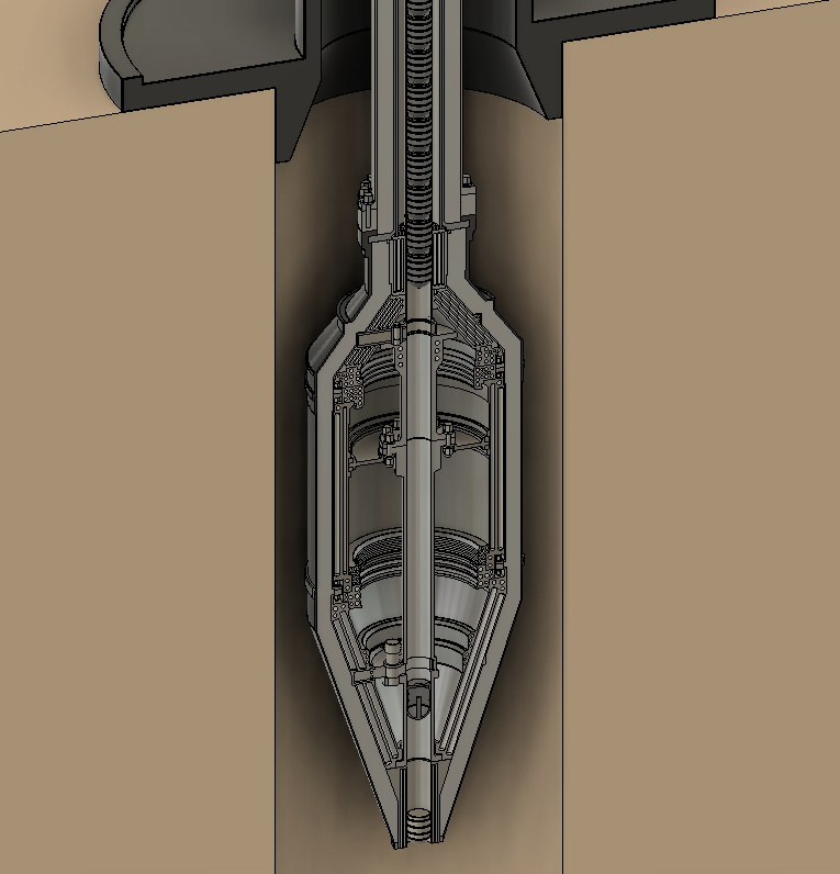
Fullscreen capture 8182022 110959 PM.bmp

The theoretical raw material-only production cost of two standard high explosives is provided below. Note that the nitrogen dioxide and ammonia costs are lower than normally advertised due to the use of our high altitude ultra low LCOE wind turbine which we would use to generate hydrogen to produce fixed nitrogen. Since RDX uses formaldehyde and ammonia to produce hexamine, the production of RDX is quite attractive and convenient since we can easily couple the system into the modular nh3 synthesizer drawing from the high-altitude turbine. The production of RDX can be done for less than $1/kg for hard raw materials only. 

Any technology that relies on consumables for its operation must be shown to be compatible with current production capacities. In our case, we must consume a substantial volume of explosive material, drilling fluid, and electricity. The explosive, due to producing a somewhat larger mean fragment size, requires a higher viscosity drilling fluid to reduce its free-fall velocity. Compared to a rotary drill, up to twice the pumping power will be required. Many people mistakenly believe that alternative or new technologies must invariably be “cheaper”, but this is a flawed notion. Vacuum tubes are clearly cheaper to engineer and manufacture than integrated circuits and silicon transistors. Rather, it is the expected performance of the superior silicon transistor that justifies its higher cost. Mechanical drilling is an archaic technology that has remained virtually unchanged for centuries, and while there exist countless alternatives, all of them share one thing in common, they are expected to be a higher-performance system but with added complexity and cost. Explosive drilling is no different.

Total explosive consumption to drill enough holes to meet all U.S energy demand. If we assume a 500mm dia well can produce 30 MWe of power with aggressive fissure stimulation, and 600 tons of explosive (5x over-use for rock comminution) are used to drill the well and 100 tons are used to induce fissuring, then we assume per MW explosive use is 23 tons. Since the U.S electricity grid is 456,000 MW, we will need 10.5 million tons of RDX. Interestingly, the U.S produced 15 million lbs of RDX monthly or 81,000 tons in the 1970s. This means to produce the entire U.S electricity grid over a period of say two decades, RDX production capacity would not have to increase by very much.

It should be remembered that these estimates are purely for scientific interest, they have no practical bearing whatsoever since extreme scenarios by definition occur in reality. It is extremely unlikely a single energy source will ever power 100% of a country’s energy budget, except for cases where it is as simple as building a demand, such as in Norway.

The realities of “hot dry geothermal”

The idea of pumping water into a rock body to induce fissuring is not new, it was developed by multiple individuals independently in the 1970s motivated by the energy crisis. Bob Potter issued the first patent on the principle. The idea is extremely simple, use a slight excess of pressure above the formation pressure to slowly enlarge existing micro-fissures. The crust is thought to be rich in tiny fissures or faultlines that exist perpendicular to the hydrostatic gradient. Since the force of gravity manifests in the vertical plane, displacing the rock tangent to the surface plane is much easier. While the permeability of the crust is estimated to be in the nano-darcy range, existing microcracks are liable to be expanded slowly over time with enough pressure, although there is considerable variability in the presence of pre-existing microcracks. Many hot dry geothermal projects were attempted in the 70s and 80s. Most notable is the Fenton hill well in New Mexico. While there were several successful runs where fissures were formed after substantial pumping effort, many wells refuse to “open” and power output remained low. An article by Richard A Kerr in SCIENCE entitled “Hot Dry Rock: Problems, Promise” chronicles some interesting findings without placing a positive spin on it. Kerr is quoted as saying “After a decade of hard lessons and limited success, tapping the enormous heat reserves in rock too dry to yield steam or hot water on its own faces more challenges”. He goes on to say: “No one has figured out why some fractures open and others do not”. “Hot dry rock has proved to be a recalcitrant, even devious foe, demanding greater respect and subtlety of design than pioneers in the field imagined”. Kerr describes how some of the wells drilled and hydraulically stimulated that performed well were because of natural openings and not due to the hydraulic fracturing itself. A major scientific error made by geothermal proponents is comparing existing hydraulic fracturing strategies used in highly brittle, soft sedimentary shale rock. Many geothermal proponents have made totally unfounded claims that somehow they can apply shale fracturing technology to extremely hard, strong, highly compressed igneous and metamorphic rock, which is highly erroneous. There is little reason to believe the mild pressures used to stimulate fractures in shale will ever produce even close to the results in deep crystalline rocks. While our proposed strategy to use the immense detonation pressure of explosives to generate thousands of bar of pressure of the background hydrostatic pressure may not even be sufficient, it is at least an attempt. One thing can be said, regardless of how successful the efforts at developing new drilling technologies are, the entire effort is ultimately determined by how much and if we can fissure deep rock strata. If it should be too difficult to reliably induce fissuring to achieve the necessary surface area and flow path, geothermal energy will remain in obscurity. This will mean any alternative drilling technology will be seen as an asset to aid in deep gas exploration in hard rock strata. It is quite astounding to see so many geothermal startups makes claims with utter confidence and certitude that once we have this magic bullet that is some new drill apparatus, all we have to do is effortlessly pump water into the hole and “voilà”, a huge volume of pore space will suddenly be generated. Considering the only successful and proven site was Fenton which was only 3 km where hydrostatic pressure is much less than at 12 km, one cannot extrapolate these results.

Another important factor is establishing the energetic inputs of pressuring the hydraulic fluid. If we assume we need a few hundred bar of additional pressure of 500 bar, and to generate a seismic volume of 80 million cubic meters we must inject 25,000 cubic meters, a total of 300,000 kWh is required, or about 12.2 kWh/m3 at a pressure of 500 bar. These numbers seem to endorse the overall energetic efficiency of hydraulic fracturing. Even if an order of magnitude more water was required, the power still only amount to 3 million kWh, which is a reasonable number.

It’s interesting to note that currently, there’s yet a consensus on the exact mechanism at play during hydraulic fracturing. It’s assumed the planar fractures propagating along the rock layers are slowly enlarged, but evidence suggests crack also propagate parallel to the hydrostatic gradient. Either way, until more certitude, exists on the 

Nitrogen oxide is shown instead of “nitric acid” since nitric acid has a higher molar mass than NO2 due to the addition of water which adds oxygen and hydrogen molecules to the NO2. NO2 has a molar mass of 46 grams, while HNO3 has a molar mass of 63 grams, so one kg of NO2 yields 1.37 kg of HNO3. The cost of ammonia is assumed to be $350/t (corresponding to a wind-powered plant with power costs of $0.03/kWh), since 300 kg of ammonia is needed to produce 1 ton of NO2, the cost per ton of NO2 is only $100. The indigenous in-house production of all the raw materials is essential for cost control and the production of cheap high explosives, which forms the enabling strategy for high-intensity explosive drilling. Being fascinated by explosives does not make on a terrorist, rather it makes one a keen observer of the fact that conventional high explosives are a sui generis technology. No other technology but electromagnetic coils in particle accelerators can move matter at the speeds at which conventional high explosives routinely detonate. It is precisely because explosives possess these unparalleled and sui generis properties that make them a robust candidate for making the first genuine breakthrough in drilling technology since the invention of the turbodrill in the 1920s. Outside of rock blasting, explosives find few applications in civilian engineering outside of their niche application in ballistic parachutes and airbags. It just so happens there exists a potentially enormous application for explosives to be harnessed for peaceful purposes to generate large amounts of energy. At the present time, the chief usage of high explosives such as cyclonite is for military purposes, artillery shells, missiles, and rocket warheads. There exists no civilian sector whose core technology rests on the power of explosives to perform essential functions outside of quarrying and blasting, and these sectors mainly use low detonation velocity explosives such as ammonium nitrate fuel oil or dynamite (nitroglycerine and diatomaceous earth). One such application as we have discussed already is drilling deep holes in the earth faster and more efficaciously than with rotary bits. But perhaps a more important and unknown application is their ability to induce the fissuring of rock at great depths. Even if a conventional rotary bit can suffice albeit with reduced performed, the whole can no doubt still be drilled. But one this borehole has been drilled, from a geothermal perspective, it’s utterly useless. For conventional hydraulic fracturing to work, water must be pressurized above the surrounding rock pressure, otherwise, the water does not possess the necessary force to break the rock. Rock cannot be broken by water and a lower pressure than itself! Horizontal “fracking” for oil and methane occurs at shallow depths compared to what is needed for geothermal, making it unsuitable and ineffective for geothermal fracturing. This means there presently exists no technology for generating large fissure volumes for water to capture the necessary heat from the rock. It’s irrelevant how good drilling technology becomes, even if we had a brilliant drilling technology invented tomorrow, there exists no method to flow water into non-porous rock formations. This effectively restricts geothermal technology to geologies where highly porous rock already exists and or aquifers. This is where we are currently in the so-called “geothermal industry”, which is a misnomer because there is no geothermal industry. Hydrostatus Systems has proposed the only physically possible fissure formation mechanism available. We have called this technology “Downbore fissure formation using high explosive charges”. Conventional geothermal technology is not just limited by poor drilling technology, it is limited by the inability to reach a large rock mass to capture sufficient energy. Hydrostatus Systems has devised a scheme to use the explosive drill to bore large diameter shafts up to 15 kilometers deep and place insulated binary liquid explosive charges consisting of tetranitromethane and toluene to induce massive fissure growth to achieve power outputs in excess of 50 MW per wellhead. The charge would be filled in situ and quickly detonated minimizing heat transfer into the explosive chamber. The size of the explosive chamber is limited by the diameter of the well, this is where explosive drilling comes in, because it can facilitate much wider hole drilling than rotary drilling, a much more powerful shaped charge can be placed in the wellbore. The weight of the charge could reach 1000 kg, which is a substantial size bomb roughly the size of the typical truck bomb, which can level entire concrete buildings. The larger diameter of the bore allows for reduced heat transfer, allowing the explosive more residence time needed for capping the well. If the casing of the hole is relatively smooth and lubricated, the explosive charge can be descended quite rapidly. The issue is then insuring that the well is properly capped. It may be required to insert along the entire depths series of solid metal or hollow-concrete-filled shafts to absorb, although this may pose issues with recoverability. If the mounting mechanism on these shaft sections is damaged by the explosion, it may be impossible to recover effectively making the well useless. A better option may be to merely fill the area above the charge with water and place a very heavy mass above it. Since the explosive cylinder would be a shaped charge, the direction of shockwave propagation is downward, and while the recoil would be immense, it would be well within the ability of current engineering to prevent any major blowback from occurring. The concept of using explosives to stimulate geothermal wells to fissure allowing a large area for water to flow is not new. During the so-called energy crisis of the 1970s a report by the DOE titled High-temperature explosive development for geothermal good stimulation” and another report titled Explosive stimulation of a geothermal well: GEOFRAC“, and another report by Lawrence Livermore titled Explosive Stimulation of a Geothermal Steam Reservoir” all studied using explosive charges at the bottom of the well to induce large fissure growth in the rock. The primary issue encountered was the poor temperature resistance of most explosives compounds, liquid and solid alike. Since the explosive charge has to be placed before the well is capped, the charge may have to spend several hours in the well before it is detonated. The second problem is that since in most of the reports highlighted they only placed a single consecutive charge, the actual volume of rock fissured was minimal and had little effect on the productivity of the well. If an explosive charge can barely induce fissuring, one must ask the obvious question: how on earth can lowly pressurized water induce it? The answer is of course it can’t, hydraulic fracture is impotently hopeless in the hydrostatic pressures encountered at the targeted depths. 

The DOE even considered using fission devices to induce fissuring. Such an option would be extremely effective and generate a water flow area so large as to extract potentially thousands of megawatts per wellhead. Since the cost of a geothermal well is directly a function of how much power can be extracted per well drilled, the ability to induce massive fissures using nuclear weapons may be extremely attractive. It is anticipated political issues would thwart any such effort in Western countries, but non-Western countries may take up the challenge. It’s conceivable that if hydrocarbons are being depleted and climate change concerns continue to be so grave, this option may be a necessity for geothermal to ever be widely used. Below is an image from the Cannikin explosion that took place on the Amchitka Island in Alaska where the Atomic Energy Commission drilled an 1800-meter deep hole 2.2 meters in diameter and inserted a 5.5-megaton thermonuclear warhead. The image illustrates the fissures that would be predicted to occur from the detonation. The entire Amchitka island incurred a massive crack, no induced seismicity occurred despite concerns. It is almost impossible to imagine anything like this happening today, the stultifying political and cultural environment has put the brakes on any extraordinary engineering, all we’re allowed to do is code HTML and Starbucks. Although it is unlikely such a powerful blast is actually needed, consecutive detonations of 800 kg high explosive charges will likely produce enough fissures to generate satisfactory power output. Ignoring radioactivity concerns, there are also serious logistical and technical issues with using even miniaturized fusion devices. Such warheads firstly have to be manufactured and made available to certain government-approved entities. presently, these are not legally allowed to be sold to private citizens! Secondly, it must be transported, stored, and inserted into the well. Insertion into the well is by no means a massive technical challenge, but transporting a warhead to the site, especially considering thousands of these wells will be drilled, would be unpalatable. Either way, it is interesting to realize that Hydrostatus Systems is the only engineering firm in the world that is proposing this combination of technology to massively potentiate geothermal energy. Since the original 1970s DOE report, no attempt to drill holes and inserts high explosive charges for fissure formation has been attempted nor are any “startups” pursuing it. This is unsurprisingly considering today’s engineering climate where gimmicks and magical technology are what occupy everyone’s time. Modern-day Western engineers are preoccupied and wasting their time with “e-mobility”, a complete technological boondoggle, to bother pursuing genuinely useful innovations.

High explosives, nuclear or conventional, are the only technology available to actually generate a large surface area needed for heat transfer to be rapid enough for the will to capture a large volume of rock.

The way to understand heat transfer kinetics in the rock is by creating an arbitrary 3D coordinate system to visualize the series of rock layers that surround the flow path. In reality, there is no finite boundary, that would be absurd, there is rather a smooth gradient from hot to cold.

A simple thermal boundary to illustrate the flux of thermal energy from a hot body to a cold body. In this case, a cylindrical shaft is inserted into a arbitrarily large block of material with the assumed density of 2650 kg/m3 and a thermal conductivity of 2.1 W-mK.

The rock consists of primarily silicon and oxygen atoms, often with metallic cations, which are vibrating, if the vibrating atoms on the inner section facing the water flow surface begin vibrating more slowly, an exchange of energy will occur. For an exchange of energy to take place, there must be a deficit of energy on one side. Since a geothermal well is not a continuously heated system, it draws down the thermal budget of a fixed rock mass that can expand in radius indefinitely across the system’s lifespan. If heat is drawn faster than it can be replenished, the cooled area will expand effectively growing the size of the water flow area which initially starts at only a very small radius. Heat drawdown can be visualized as a process of “consumption” where the cold water eats away like corrosion at the energy around it. The cool area grows, the hot area shrinks, but the same amount of energy still flows across the circuit because the total temperature remains constant. By definition the rate of heat transfer must equal the area that is traveled by the energy over the operational duration, this is measured as thermal diffusivity and is discussed in more detail earlier. Cold inlet water is continuously fed through the pipe, as heat is removed from the inner section, heat then moves the outer section and replenishes that section that was just drawn, this is then immediately depleted and the cycle repeats. But each time this occurs, the radius that heat must travel increases since each time there is a deficit of energy below what is needed to replenish the rock, so the rock gradually cools further away from the radius, but the total flux of energy remains constant since the temperature difference remains constant only over a larger area. This larger area that heat must travel to reach the inner section is why well power output declines of the life of the unit. Any estimate of a geothermal well’s power output that is not the average of its operational life is worthless. The output of the proposed 360mm diameter mono-bore is 16 times more in the first hour than over its 100 year life. This is because the thermal penetration distance is squared. The diameter of the hole, the type of fluid used, the rate of fluid flow, the type of powerplant etc, make no difference whatsoever on the available thermal energy that can be drawn from a geothermal well. It is exclusively and solely a function of the rate at which heat can propagate over a given distance over the lifetime of the unit. Any claims otherwise are marketing gimmicks.

Below are quite detailed calculations and estimates of the system’s performance, cost, and lifespan. The estimates are based on using the current data available for rock thermal diffusivity, heat capacity, and density. The earth’s crust is highly heterogenous and many geographies may feature rock with a poorer thermal conductivity than others, which may affect the output of the well, but this occurs both ways, since our estimate is based on the “mean” rock of the crust, which by definition doesn’t really exist, since the crust is made of dozens of different minerals. The system is assumed to be a closed-loop vertical well-bore with no down-bore rock fissuring since down-bore fissuring has yet to be proven. In this case, the well is effectively a vertical straight version of the so-called “Eavor-Loop”, a Canadian geothermal company that has proposed obviating the need for fissure formation by drilling a series of horizontal loops. Since Hydrostatus Systems believes it is finally possible to drill relatively deep inexpensive holes with detonation drilling, we can simply drill a bunch of straight holes in the earth and merely cool the surrounding rock without needing any fissure formation or horizontal drilling. Developing a large flow area at the bottom of the well may prove impossible, even with down-bore conventional explosive charges, so Hydrostatus Systems views straight-bore technology as perhaps the only realistic option achievable in our lifetimes.

It should be said for investor transparency that the power of a geothermal well cannot be estimated without engaging in pure conjecture and yielding grossly incorrect estimates which are useless and dangerous. Just like a gas or oil well cannot be estimated, neither can a geothermal well. What can be said is that if the well does indeed employ the techniques we suggest to drop large high explosive charges one after another to fracture a radius of rock around the bottom of the well, a higher degree of confidence may be attained.

The “power density” of a kg of the crust’s rock is less than that of an ant!

People have a difficult time grasping just how minuscule a quantity of energy a given mass of rock actually possesses. Because the deep earth is viewed as being inherently “hot”, people intuitively assume it possesses a huge amount of practically “infinite energy”, which as we have previously discussed, is far from the truth. This might be true on a macro scale, but at a microscale, where it is relevant for a geothermal well, the energy available is truly minuscule. If we assume the geothermal well we drill will be used for a century, the total area cooled (thermal drawdown region) over its lifetime is a fixed radius around the wellbore center whose size is directly proportional to the thermal diffusivity. This radius happens to be around 90 meters for a thermal diffusivity of 0.65 the average for the crust at 300°C, with a heat capacity of 1150 kJ/kg-K. To draw 20 MW for a hundred years will cool a mass of rock approximately 1.3283628 × 10^12, (one trillion three hundred twenty-eight billion kg), which is a mass of rock that is almost impossible to grasp by the human mass. The volume assuming an average density of 2650 kg/m3 is 5.01268981 × 10^8 cubic meters, or a dome 1300 meters wide and 600 meters tall. This means our geothermal well must cool an area of rock twice the height of the Eiffel tower with a diameter of 1.5 times the Burj Khalifa’s height. The average amount of power extracted from each kg of rock is only 15 microwatts (0.015 milliwatts), or 1.50561277 × 10⁻⁸ kW. This is an infinitesimally small power density, around ten million times lower than a lithium-ion battery, which is already one of the lowest power-density energy systems out there. In summary, rock has just a tiny fraction of the energy density of solar energy, wind, tidal energy, or even animal power. The only reason it’s technically viable is due to the sheer mass of the rock that forms the radius around our well, since the well forms a 15-kilometer deep tunnel, the total mass of rock tapped is simply humungous, even though it only yields a sum of energy that is lower to the caloric budget of an insect. Cataglyphis bicolor, an ant, has a metabolic energy of approximately 30 microwatts when crawling at its maximum speed. The earth is simply so gargantuan, even though we are drawing just microwatts from a kg of rock, it represents a massive aggregate sum of energy. The land area occupied by each 100-yr well is 0.038 km2, since each well generates around 20 MW, the power density is 518 MW/km2, which is about 17.3 times better than high-altitude wind. Since we have in the U.S around 250,000 km2 at 35°C/km, we can theoretically produce 128,750,000 MW, or 9 times global energy consumption for a hundred years, or current energy consumption for 919.6 years. At current human lifespans of 85 years, this represents the upper limit on human time horizons, since the probability of catastrophic civilization-destroying events (nuclear war, pandemic, asteroids, dysgenics, etc), occurring in this timeframe is considerable, it is of little use to extrapolate such a long time. This tiny of amount of energy on a volumetric basis is also reflected by the very sluggish heat transfer dynamics. If we have a body of rock with a thermal conductivity of 2.1 W/mk and we pass water that is 100°Cthrough a pore at 565°Cthe thermal flux is only 50 watts per square meter, meaning that if we wanted to extract 30 MWt from a well, we would need to induce a total of 2,000,000 square meters of fissure area. Thankfully, due to the high degree of asperity of these fissures, the specific surface area would be immense.

Since the availability of high-altitude wind power is limited to sites with wind speeds in excess of 10 meters per second, and there is a potentially serious risk of “terrestrial stilling” caused by climactic warming due to so-called ‘polar amplification”, we have hedged our bets and investigated geothermal as an alternative. As usual, Hydrostatus Systems does not merely assume the industry dogma to be valid at face value. In fact, many of the assumptions and customary methodologies employed by the geothermal industry if there exists such a thing are dubious. Attempting to fracture rock at great depths is simply a technical challenge beyond our present capabilities, hence the development of the mono-bore. Since few sites feature attractive natural aquifers to tap into, if geothermal is to ever scale, a technology is needed to obviate the need for both rock fracturing and aquifer availability.

High-altitude wind technology is forced to compete with three major forms of alternative energy technologies. The first and most well-known and proven of these alternatives is the trusty silicon boron-phosphorous doped polycrystalline photovoltaic module. The second is geothermal, where holes are drilled in porous rock media, and water is flowed up to the surface as steam. The third is hydropower, intuitive enough to not need an introduction. The fourth is fission, where uranium 235 is fissioned in a moderated light-water reactor core. This technology might be pollution-free, but it’s not even remotely close to renewables. If scaled to meet eventually world energy demand, all the world’s accessible uranium would be burned up into iodine, cesium, strontium, xenon, and barium within a few years. Since we have analyzed photovoltaics quite extensively, it would make sense to rather briefly analyze geothermal technology to determine whether it can ever be a viable competitor. The short answer is that it will not be a large-scale contender in the alternative energy landscape for a simple physical limitations: the low thermal conductivity and more importantly the low thermal diffusivity of rock. Interestingly, many might believe the issue is merely technological, and that improvements in say drilling technology can make it viable, but this is not really the case.

Many people believe the issue with geothermal is that either we lack the appropriate drilling technology, or that the temperature is not high enough at accessible depths to make it viable. Neither of these facts is really correct upon close examination. There are at least 100,000 square miles of area available where gradients are up to 50C or more per kilometer. Around 12,000 square kilometers in Iceland are available at 55C/km, and around 120,000 or more are available in Australia where gradients approach 47°C/km. Since energy is defined as a change in temperature, to draw a meaningful amount of power from a geothermal well an insignificant drop in temperature is needed. The less the temperature in the well, the smaller the minimum temperature drop can be.

About 3% of the U.S land area, mostly in the Western desert, is at 35°C/km or more. 35°C/km is the minimum for a viable powerplant. Australia, Iceland, parts of Western Italy, and Anatolia are more optimal sites, but excluding Australia, land restrictions may be an issue.

Most of the world has a gradient of around 30°C/km, which is insufficient to justify drilling an elaborate well. The petroleum exploration industry has successfully drilled more than 10,000 meters with rotary bits around 200mm in diameter. The deepest hole ever drilled in the earth is in Siberia in the Sakhalin-I gas complex. The depths approached 12 kilometers. Since water or oil is used as the drilling fluid, the drilling bit is subjected to pressures of 1000 bar or more at this depth. Conventional drilling technology is limited to a speed of at best 10 meters per hour, but the deepest drilling occurs at a snail’s pace of only a few feet per hour. 39% of the upper crust consists of plagioclase feldspar, 12% as Alkali feldspar, 12% as quartz, and 11% as pyroxene. The average hardness of feldspar is very high, with a Mohs hardness of 6-6.5 (Vickers hardness of 900 kg/mm2), equivalent to a Rockwell°Chardness of 55. In comparison, hardened steels machined using tungsten carbide typically achieve hardness levels of around 45 HRC or a Vickers hardness of 270 kg/mm2. This means it requires three times more force to grind feldspar than hardened steel. When cutting hardened steel, carbide inserts rarely last a single hour. Rock drilling bits use diamond cutting inserts, the inserts are made not of solid diamond, since the cost would be prohibitive since growing large diamonds is a very slow process. Instead, they use polycrystalline diamond powder manufactured using periodic explosive charges to create shockwaves and local pressure zones which induce the graphite powder to form the allotrope of diamond. This type of polycrystalline diamond costs around $500/kg, but since it has no structural integrity on its own, it cannot be formed into a solid rigid shape unless a binder is used. Binders can be either metallic or resin, since resin decomposes and or loses most of its strength at relatively low temperatures, metallic binders must be used. But since metal is much softer especially at high temperatures compared to rock, the metal binder is rapidly abraded and the diamond tool piece is rendered useless after just hours of use. Since only a few feet can be drilled per hour at great depths, the bit must be pulled out along with the entire drive shaft every few hours. The total time to drill a 12-kilometer well could be multiple years including withdrawal and shaft removal and reinsertion. Since the shaft can only be as long as the length of a semi-truck and is limited by the height of the rig unit, most shafts are no longer than 15 meters. This means that if the drill bit is inserted down to 12,000 meters, if the bit wears out and needs to be replaced, a total of 800 shaft sections must be removed and placed somewhere. The process then has to be repeated 800 times. The book series published by Springer titled “Exploration of the Deep Continental Crust” contains following texts, The German Continental Deep Drilling Program (KTB) Site-selection Studies in the Oberpfalz and Schwarzwald by Rolf Emmermann and Jürgen Wohlenberg, published 1989, Deep Drilling in Crystalline Bedrock Volume 2: Review of Deep Drilling Projects, Technology, Sciences and Prospects for the Future by A. Boden and K.G. Eriksson published in 1988, Super-Deep Continental Drilling and Deep Geophysical Sounding by Karl Fuchs Yevgeny A. Kozlovsky and Anatoly I. Krivtsov published in 1990, Observation of the Continental Crust through Drilling II Proceedings of the International Symposium by Hans-Jürgen Behr and Francis G. Stehli published in 1987, and finally The Superdeep Well of the Kola Peninsula by Yevgeny A. Kozlovsky. Hydrostatus Systems used the search function with the keywords “drilling speed”, meters per hour feet per hour, feet/hour, meter/hour, etc to find mention of drilling speeds. The results were successful and turned up a chart showing the achievable drilling speeds as a function of downward force and RPM. The chart below suggests with an intermediate RPM of 400 with a shaft force of 8 kilopounds, the speed can reach 8 feet per hour. This would suggest the drilling time alone for the 12 km well would be 5000 hours excluding bit withdrawal time.

Since conventional rotary abrasive drilling is a very slow process, requiring periodic bit replacement, the suspension of the heavy torque shaft, the need for a large rig to carry its mass, a propulsion system for providing the torque, and the issue with binding and shaft friction along the bore walls, a number of alternative methods have been proposed in an attempt to finally make geothermal a genuine contender in the energy landscape. But considering the Soviets drilled a hole 12 kilometers deep in crystalline bedrock quite successfully with 1980s technology, why should we believe this? If the energy available at these depths were so great, we could easily justify the 10-20 million dollar investment to drill 10-12 kilometers no? the reality is quite obvious to those with knowledge of thermodynamics, unfortunately, most people lack this and fall victim to fantastical claims about “infinite energy” available in the earth. An entire array of alternative drilling contrivances have been suggested, ranging from plasma vaporization, thermal spalling, projectile launchers, explosive capsule ejectors, and water jet spalling, among others. None of these alternatives have been commercially deployed, and while they appear attractive in theory, there is too much multiplicity considering the extreme conditions they face, hundreds of degrees °C, and hundreds of megapascals of hydrostatic pressure. Even the most well-designed drilling system faces intense stress during its operation and considering conventional rotary drills have such a proven track record, any contender faces a steep battle to compete with them.

Rock is not an “infinite source” of energy

Aside from drilling, which is likely improvable with better technology, the critical limitation is not technological but rather purely physical limitation arising from the sluggish thermal diffusivity of crustal of rock, of which the most common is plagioclase feldspar. The upper crust is assumed to have a thermal conductivity of 2.1 W/m-K, with a relatively high heat capacity of 800 J/kg-K. With a moderately high density of around 2650 kg/m3, these numbers translate into a very sluggish thermal diffusivity, the most crucial variable in determining how fast we can “draw” heat from a rock mass. Many people mistakenly assume thermal conductivity is the only metric that matters, this is incorrect. Thermal diffusivity is the crucial variable because it is a direct measurement of the propagation rate or speed at which thermal energy (heat) travels across a surface of a material measured in square meters or millimeters per second. Thermal conductivity in theory is such a measurement, since it measures the total flux of energy across an arbitrary body with a given temperature difference, but it is not material invariant. Thermal diffusivity is arrived at by dividing the thermal conductivity by the heat capacity multiplied by the density. Thermal diffusivity, unlike thermal conductivity, takes into account the material’s ability to absorb heat as it conducts. When heat flows through which has a temperature gradient (which is a tautology since no heat can move without a gradient) some of the heat is reabsorbed by the material’s depleted heat capacity, thermal diffusivity adjusts for density and conductivity and heat capacity to estimate how fast thermal energy can move in a solid material, gas or liquid. A material with a low density, high conductivity, and low heat capacity, will have a high thermal diffusivity since there is little mass and heat capacity to absorb the energy that is propagating across the material. Conversely, if the material has low conductivity, high density, and high heat capacity, the thermal diffusivity will be sluggish since the bulk of the energy traveled is reabsorbed by the dense high heat capacity material. It might seem as if we want a high heat capacity in our rock, after all, if we reduce the temperature of a given rock mass by X amount, the power available is directly a function of the heat capacity. But unfortunately, the situation is not so simple, because if we draw down an arbitrary section of rock around or geothermal well flow area, we have temporarily “stolen” the heat of that rock and transferred it into our flowing water which is then pumped to the surface. This energy has been permanently removed from the rock. If we then continue to draw heat down from this rock mass since our water is still flowing, we will now be pulling heat from an arbitrary rock section slightly further away from the well water flow area, so heat must now have time to flow across the just-depleted rock. But since we are constantly sucking heat out, this energy that is now flowing due to the temperature difference will not go to replenishing the rock since we are constantly depleting it, the difference between the depletion rate and the supply rate is proportional to the mean distance between the drawdown distance. As this process repeats, the radius of “thermally drawn” rock will grow ever so slightly around the water flow area infinitely until after millions of years, and the entire crust is cooled to the temperature of the water. Since heat flow is a function of temperature difference, the more we cool the rock the more energy actually flows, so in that respect, this is what we want. But since this heat flow is immediately captured, the rate at which this heat flow travels from the outer radius of the flow area to the center determines the amount of energy we can extract per hour. The mathematics now becomes interesting, because the equation for thermal penetration length or thermal penetration rate is the square root of 2 times the thermal diffusivity coefficient and the time, thermal penetration is thus directly proportional to the square root of time, but. Therefore, the speed at which thermal energy propagates is very fast at the center but slows down logarithmically towards the outer radius. If we double the elapsed time from which heat can travel, the distance reached grows by only 1.4142 times. This inverse logarithmic relationship causes wellbore output to sharply fall in the first few hundred hours of operation and then level off only very gradually declining. 1.4142 is an irrational number and happens to be the square root of 2. The equation is written as √2αt, where α is the diffusivity coefficient and t is time. The diffusivity coefficient is also sometimes denoted as d or k. Hydrostatus Systems created a solver using fxsolver.com in order to simplify the calculation by allowing one to solve for distance, time, or diffusivity coefficient, most other calculators on the internet only allow one to solve for distance. In order to ensure our calculations are correct, we compared it to the calculator below offered by Thermtest, the results are identical. https://thermtest.com/thermal-resources/heat-penetration-calculator#thickinput_125,diffinput_1.1,timeinput_3600

Thermal Penetration distance: √2αt

It would be remiss to ignore other technical issues with geothermal besides the low thermal diffusivity of bedrock. Another issue is the fact that the water cannot be heated to the temperature of the rock or else no heat transfer will occur, yet the water desires to be as hot as possible for efficient conversion in a Rankine cycle. Since most nuclear reactor steam turbines draw steam at 315°C, their efficiency is only about 30%. If the water temperature is only 250°C, the efficiency can drop below 20%. For any heat transfer to occur, there must exist a substantial difference, this means that the mean temperature of the water must remain well below the temperature of the bore, this requires to flow at a rate substantially faster than the ability for the water to warm otherwise it will simply rapidly rise to the temperature of the surrounding rock and heat transfer will slow down to very low levels. If we are pumping 20°C water from the surface, depending on the flow rate of the water, heat transfer will continue to occur until the rock has cooled to some equilibrium at some midpoint between the rock and the water. This depends on the diameter of the flow area, since water has low thermal conductivity, its much easier for heat to flow through the hot rock and into the cold water than for heat to flow within the water. This equilibrium is always going to be lower than the ambient temperature of the uncooled rock. This means if the bottom of the geothermal well is 660°C (55°C x 12 km), the water must be kept at a mean temperature of only 350°C, or less than half the average well temperature, since it will very quickly reach a high fraction of the mean rock temperature if flowed relatively slowly. If the water is flowing fast, the rock cools faster but the heat transfer increases. If the water temperature is allowed to fall significantly below the surrounding rock media at the end of the flow area corresponding to the end of the bore, the temperature difference between the minimum desired turbine efficiency and the surrounding rock temperature determines the heat flux. Therefore, a good compromise is made around 410°C below the 660°C bore, which maintains decent turbine efficiency but allows for very rapid sufficient heat transfer to occur. Of course, this can only be achieved in sites with high thermal gradients, otherwise, the temperature difference between the minimum turbine temperature requirement and the available heat of the bottom of the rock flow area is too small for sufficient power extraction. This might sound confusing, but the central reason why its a problem for geothermal wells is that unlike a real heat exchanger say using combusted flue gases to warm water, the bulk of the heat transfer occurs rapidly across a very small surface, in other words, the specific heat transfer rate is huge because the energy input is unlimited, it is impossible for the working fluid to pull enough heat to cool the flue gases passing through our heat exchanger. On the other hand, in a geothermal well, the flow path is very long which means the heat transfer is dispersed across a large area as well as a large increment of time. This means the water is quickly warmed from the initial flow trajectory, but then only slowly captures heat from the rock further along its flow path. But since the initial rock loses most of its heat and transfers it to the water, the heat transfer from then on is sluggish.

Corrosion of the borehole liner is another issue for geothermal wells. Casing is required not to withstand the hydrostatic pressure, but to prevent erosion and gradual decay of the rock hole and to prevent sediments and rock fragments from contaminating the water supply. Since cathodic protection may generate hydrogen and cause embrittlement of high-strength ferrous alloys, most bore liners are unprotected and barely last a few decades due to the high presence of sulfur and chloride compounds in the surrounding rock. Another challenge is related to supporting its mass during its installation as it descends into the multi-kilometer shaft. If the bore liner is not supported on a ledger on the side of the bore wall, which requires tapering the bore which adds considerably drilling hassle, then it must be suspended in its entirety as its welded and lowered into place. A further issue is heat loss as the hot fluid flows up through the cooler rock at shallower depths, which might result in half of the total energy being lost to the cool rock in the upper half of the up to the 10-kilometer-deep shaft. But by far the single biggest limitation is heat transfer, not drilling, bore-liner, or heat losses, which are amenable to technological enhancement. Ultimately all technologies have physical limits that place a strict cap on their performance or output, a Shockley Queisser limit for photovoltaic, a Betz limit for wind, a Carnot limit for heat engines, and a number of less-known physical limits on a host of other technologies. Technology can only improve the way an artificial mechanism can perform a natural phenomenon, it can only improve it to the extent the natural phenomenon is amenable to process efficiency, and it cannot in any way alter the natural phenomenon itself.

It bears repeating that most people mistakenly believe drilling technology is the “Achilles’ heal” or “limiting factor” for geothermal, but this is wrong. The central issue is creating a surface area large enough for heating a sizeable portion of water, sufficient to make drilling the well economical.

The critical weakness that effectively forbids its wide-scale deployment is the difficulty of establishing a flow path between the inlet and outlet boreholes. For any sizable power output, the system must employ what the industry calls a “closed loop” circuit, where working fluid is pumped down into an inlet well to be heated and then pumped back out. The pumping energy is usually provided by a thermal driving head, the so-called “thermosyphon effect” where the difference in hydrostatic pressure is used to overcome the viscous resistance. But this difference in pressure may not be enough to compensate for pressure drop and pumping power may be necessary for very high flow rates. For a sufficient surface area to be created to heat the flowing fluid, a large amount of rock has to be shattered horizontally at kilometers of depth to allow water to establish a circuit. A highly porous flow path has to be established, this can in theory be performed by pressurized water above the hydrostatic pressure, but practical considerations make this extremely difficult. Firstly, the fracture has to be in the right direction, pressure desires to flow in all directions at once, merely pumping water into the well above the hydrostatic pressure is no guarantee that the fracture will occur straight between the two shafts and form a perfect path between them. Secondly, the amount of pressure needed above the hydrostatic pressure is substantial, which means the water must be pressurized starting from the beginning of the hole at the surface, requiring massive pumps.

Present-day geothermal relies on so-called “hydrothermal” architecture, which taps into natural reservoirs, most Icelandic plants employ this principle. The power densities of this configuration are very low. The only way to scale it is to pump water down into the borehole. But to pump water down into the borehole requires that water to flow horizontally at sufficient volumetric flow rates as it encounters viscous pressure drop due to the porosity of the rock, if the pressure drop exceeds the thermal driving head, then the flow is limited or requires pumps.

After about five minutes of studying how present geothermal wells operate, it becomes evident they are severely handicapped. The only present strategy that could possibly provide enough energy is through drilling two holes and hopelessly trying to use the pressure of water to find its way through the dense rock formation to form a circuit. An alternative option and the more common method is to simply drill a hole and hope that water is already down there and simply draw out the steam without putting any water into the ground, this is what they call “hydrothermal”, but its power output is severely limited. The central disadvantage of this method is the high viscosity of steam. Steam has a much higher viscosity than liquid since it is a gas and is compressible, thus the pumping parasitic power caused by friction along the borehole wall causes a drop in the pressure limiting the available flow rate. 

Heat transfer is bottlenecked by the rock. Assuming a heat capacity for rock of 500-1000 kJ/kg-K, a thermal conductivity of 2.1 W-mK, and a temperature drop of 270°C, the available power is only 90 MW-thermal for a 15 km well in a 55°C/km geography.

In summary, geothermal energy is effectively technically difficult, not saleable, but potentially very cheap, so it is attractive, but not a “game changer” and will never be used on a large scale due to fundamental thermodynamic limitations. We can thus confidently conclude that outside of major innovations in fission, such as potentiated reactor designs and or safe breeder reactors, no major energy panacea will arrive, leaving high-altitude wind turbines as a very potent contender for decades if not centuries to come.

A substantial portion of the earth’s heat core and mantle heat budget is residual heat from its formation, the balance is isotopic decay. Anyone who claims geothermal is renewable is ignorant of thermodynamics, of which many people unfortunately are. Photovoltaic in comparison is not a finite source because one is tapping into a constant stream of photons, and it would be by definition physically impossible to capture more of them than are arriving because it would require an invisible solar panel to allow them to be stacked in front of other! Since a solar panel can only capture 18% of the prevailing ultraviolet and visible flux, one cannot drain down this source, only tap it to its maximum. Wind is like solar, you cannot pack more wind turbines in a square kilometer than the minimum wake losses permit, so once you max out the area, the energy source is tapped out, but it does not decline since only a tiny fraction of the wind’s kinetic energy is captured by the turbines and in theory, keeps going on forever as the wind blows. Wells will only be drilled in regions where the crust’s rock composition has high thermal conductivity or a close distance from magmatic intrusions. Rock has high density and high heat capacity, but very low thermal conductivity, which means slow thermal diffusivity, a measure of how fast heat penetrates into a body. This means that if you drill a well, if you draw more than the thermal diffusion rate can resupply it, the well will rapidly cool. This limits the amount of power extractable to between 9.5 and 19 watts per kg of rock over its lifetime depending on the geothermal gradient and the minimum temperature required by the steam turbine. The power density by area is much greater since we are drawing from a very deep mass of rock the entire depth spanning from the well bore to the surface. Hot regions don’t necessarily produce more energy by land area, because more heat is drawn from these regions in a shorter time frame, since the temperature difference between the hot water going to the stream turbine and the temperature of the rock is greater than what can be allowed for in a cold region. So a sharp thermal gradient, such as in Iceland, some parts of Australia, the Pannonian basin in Hungary, and Western Anatolia, will allow for a higher energy density, but will be more quickly drawn down since the T2 is greater. The available power from a well is very easy to calculate. Simply find out how long the “thermal drawdown” period is in seconds (this is the desired well life and an entirely arbitrary number), multiply that by the thermal diffusivity coefficient, multiply it by two and then arrive at its square root. This will give the distance of thermal penetration across the elapsed time-frame. Then take this distance that heat travels in fifty years and add up the volume of rock that represents and find the energy that a given temperature drop represents. It is very simple and one cannot decide the mathematics with fancy technology. The velocity of thermal diffusion is the inverse square of the distance, if distance increases by two times, the time taken grows by four times. As the thermal drawdown region grows in a radius around the pumped liquid flow path, the power output of the unit declines. It makes no difference whether you extract heat from the sides of the well, a fissure at the bottom, or from horizontally drilled holes like EavorLoop is trying to do. The geometry, surface area, orientation, or number of flow paths has no bearing on the thermal budget of the region that surrounds these flow paths. In fact, many people assume going deeper results in more energy, but as most things are counterintuitive, the reality’s the opposite. While the total heat flux is always greater at high temperatures because the potential temperature difference can be raised, the rate at which heat is replenished actually drops significantly more than at lower temperatures. This is because the thermal diffusivity is thermally dependent, hotter molecules are vibrating more intensely and repel each other and inhibit heat transfer. Since we have mentioned many times before that thermal diffusivity is the sine qua none, drawing the bulk of the heat from greater depths actually slows down thermal penetration. This means that the thermal drawdown regions grows slower and hence the mean power density falls.

Thermal diffusivity drops for all rock types as temperature increases. Thermal diffusivity does increase with pressure since the atoms of the rock are packed more tightly together, but the increase is very gradual and thus the hydrostatic gradient does not compensate the loss from temperature. For a 55°C/km gradient, the mean temperature of the well be 465 C, at this temperature, the thermal diffusivity is only 0.65 mm2/s, dropping from over 1.5 at 100°C.

Because thermal penetration speed is the square of 2 which is an irrational number of 1.412, the decline is very sharp in the first few hundred hours and then drops gradually until reaching a roughly steady state point with negligible decline. If you drill in a region where the flux is say 55°C per kilometer, which is the average for approximately 12,000 square kilometers of the entire island of Iceland, if you sucked all the heat out of a radius of say 70 meters around your well, you would produce about 30 megawatts of power of a 50 year period. But you have cooled a mass of rock that weighs 6.7 x 10^11 kg by 300 degrees, that energy is now gone, and to get more energy the heat has to come from rock further away, and this takes time. Where thermal gradients are no greater than 35°C/km (many parts of the Western continental U.S), the energy density per well (not area) is lower, about half the 55°C number, since you cannot cool the rock by the same magnitude due to the limit imposed upon by the steam turbine’s minimum Carnot temperature. If you drilled a 15-kilometer hole at a 35°C/km gradient and cooled the rock by an average of half its nominal value, in this case, it would be an average well temperature of 297°C across the entire depth, the allowable drop in temperature is thus only 148 degrees, the power is 14 MW, or 722 MW/km over fifty years. If we then take all the land of the parts of the Western U.S that have a gradient of 35 degrees per kilometer, we get a number of about 12 times global energy consumption for only fifty years, then that heat is gone forever and you have to forage in the cooler regions. Painstakingly taking the U.S geothermal gradient map and adding up the fraction of the area at 350°C, I concluded about 2.89 percent of U.S land is at 350°C/km, about the minimum for cost-effective drilling, or about 232,947 km2 in the lower 48 states, of which 90% is West of the rocky mountain range in the high plateau deserts. If all this land were tapped, the output would be 168.18 million MW. This estimate is from a recent study on geothermal gradients, a report by the U.S DOE from the 1980s that a total area of 3 million square kilometers exists in regions with thermal gradients are in excess of 30 C/km, with a total potential heat flux of 1.74×10^12 terawatt hours, assuming a 20% conversion efficiency, 3.48×10^11 terawatt hours is available as electricity. The total U.S electricity grid uses 4,000 TWh, if all the geothermal sites were tapped out to 10 km, which is conceivable since the scalability is effectively unlimited due to the non-use of scarce elements, we could expect this reserve to last 87,000,000 years.

Any technology that relies on consumables for its operation must be shown to be compatible with current production capacities. In our case, we must consume a substantial volume of explosive material, drilling fluid, and electricity. The explosive, due to producing a somewhat larger mean fragment size, requires a higher viscosity drilling fluid to reduce its free-fall velocity. Compared to a rotary drill, up to twice the pumping power will be required. Many people mistakenly believe that alternative or new technologies must invariably be “cheaper”, but this is a flawed notion. Vacuum tubes are clearly cheaper to engineer and manufacture than integrated circuits and silicon transistors. Rather, it is the expected performance of the superior silicon transistor that justifies its higher cost. Mechanical drilling is an archaic technology that has remained virtually unchanged for centuries, and while there exist countless alternatives, all of them share one thing in common, they are expected to be a higher-performance system but with added complexity and cost. Explosive drilling is no different. It is not expected that explosive drilling should be any cheaper than rotary drilling. But what is expected is that unlike rotary drilling, explosive drills will penetrate through the hardest rocks with ease. The cost of the total system, including the capsule delivery mechanism, explosive capsule manufacturing, shock-wave attenuation system, shaft and nozzle assembly, electricity, fluid, and explosive consumption, will amount to a sum of around $20 million for a 12.5 km well. Consumables are expected to account for over half of this cost. It should be remembered that “cost” is not a subject of scientific or technical interest, since it in an inherently variable and economic factor, depending on non-technical factors such as local policy, wages, and financial/monetary aspects.

Total explosive consumption to drill enough holes to meet all U.S energy demand. If we assume a 500mm dia well can produce 30 MWe of power with aggressive fissure stimulation, and 600 tons of explosive (5x over-use for rock comminution) are used to drill the well and 100 tons are used to induce fissuring, then we assume per MW explosive use is 23 tons. Since the U.S electricity grid is 456,000 MW, we will need 10.5 million tons of RDX. Interestingly, the U.S produced 15 million lbs of RDX monthly or 81,000 tons in the 1970s. This means to produce the entire U.S electricity grid over a period of say two decades, RDX production capacity would not have to increase by very much.

It should be remembered that these estimates are purely for scientific interest, they have no practical bearing whatsoever since extreme scenarios by definition occur in reality. It is extremely unlikely a single energy source will ever power 100% of a country’s energy budget, except for cases where it is as simple as building a demand, such as in Norway.

The realities of “hot dry geothermal”

The idea of pumping water into a rock body to induce fissuring is not new, it was developed by multiple individuals independently in the 1970s motivated by the energy crisis. Bob Potter issued the first patent on the principle. The idea is extremely simple, use a slight excess of pressure above the formation pressure to slowly enlarge existing micro-fissures. The crust is thought to be rich in tiny fissures or faultlines that exist perpendicular to the hydrostatic gradient. Since the force of gravity manifests in the vertical plane, displacing the rock tangent to the surface plane is much easier. While the permeability of the crust is estimated to be in the nano-darcy range, existing microcracks are liable to be expanded slowly over time with enough pressure, although there is considerable variability in the presence of pre-existing microcracks. Many hot dry geothermal projects were attempted in the 70s and 80s. Most notable is the Fenton hill well in New Mexico. While there were several successful runs where fissures were formed after substantial pumping effort, many wells refuse to “open” and power output remained low. An article by Richard A Kerr in SCIENCE entitled “Hot Dry Rock: Problems, Promise” chronicles some interesting findings without placing a positive spin on it. Kerr is quoted as saying “After a decade of hard lessons and limited success, tapping the enormous heat reserves in rock too dry to yield steam or hot water on its own faces more challenges”. He goes on to say: “No one has figured out why some fractures open and others do not”. “Hot dry rock has proved to be a recalcitrant, even devious foe, demanding greater respect and subtlety of design than pioneers in the field imagined”. Kerr describes how some of the wells drilled and hydraulically stimulated that performed well were because of natural openings and not due to the hydraulic fracturing itself. A major scientific error made by geothermal proponents is comparing existing hydraulic fracturing strategies used in highly brittle, soft sedimentary shale rock. Many geothermal proponents have made totally unfounded claims that somehow they can apply shale fracturing technology to extremely hard, strong, highly compressed igneous and metamorphic rock, which is highly erroneous. There is little reason to believe the mild pressures used to stimulate fractures in shale will ever produce even close to the results in deep crystalline rocks. While our proposed strategy to use the immense detonation pressure of explosives to generate thousands of bar of pressure of the background hydrostatic pressure may not even be sufficient, it is at least an attempt. One thing can be said, regardless of how successful the efforts at developing new drilling technologies are, the entire effort is ultimately determined by how much and if we can fissure deep rock strata. If it should be too difficult to reliably induce fissuring to achieve the necessary surface area and flow path, geothermal energy will remain in obscurity. This will mean any alternative drilling technology will be seen as an asset to aid in deep gas exploration in hard rock strata. It is quite astounding to see so many geothermal startups makes claims with utter confidence and certitude that once we have this magic bullet that is some new drill apparatus, all we have to do is effortlessly pump water into the hole and “voilà”, a huge volume of pore space will suddenly be generated. Considering the only successful and proven site was Fenton which was only 3 km where hydrostatic pressure is much less than at 12 km, one cannot extrapolate these results.

Another important factor is establishing the energetic inputs of pressuring the hydraulic fluid. If we assume we need a few hundred bar of additional pressure of 500 bar, and to generate a seismic volume of 80 million cubic meters we must inject 25,000 cubic meters, a total of 300,000 kWh is required, or about 12.2 kWh/m3 at a pressure of 500 bar. These numbers seem to endorse the overall energetic efficiency of hydraulic fracturing. Even if an order of magnitude more water was required, the power still only amount to 3 million kWh, which is a reasonable number.

It’s interesting to note that currently, there’s yet a consensus on the exact mechanism at play during hydraulic fracturing. It’s assumed the planar fractures propagating along the rock layers are slowly enlarged, but evidence suggests crack also propagate parallel to the hydrostatic gradient. Either way, until more certitude, exists on the viability of inducing or enlarging micro-fissures in the rock bed, one cannot make claims on the scalability of geothermal energy.

Liquid explosive drilling, while a much inferior method, can still be used, but a number of issues arise. The principal issue is the very long propagation of pressure waves encountered in liquid and the production of heavy rock fragments that are difficult to remove using fluid motion. The long propagation of pressure waves in liquid limits capsule ejection frequency since the maximum interval is limited by the propagation distance of a pressure wave possessing sufficiently powerful to cause sympathetic detonation. In water, a small 20-gram charge of RDX produces an 80-bar pressure wave at a distance of 1.6 meters. This not only requires a sufficient distance to be maintained, but it also limits the maximum size of the charge that can be detonated, since larger charges produce even greater pressures, although at a linear rate. It also requires that the extendable nozzle (needed to perform flushing or suction of fragments) be extended since the offset of the nozzle must ergo increase.

But most critically, something that ultimately cannot be solved merely with better engineering, is the matter of fragment removal.

With liquid drilling, what emerges is a hydrodynamically determined fragmentation and comminution cycle, which acts as the rate limiting step.

All processes possess what could be called a “rate-limiting step”, a term borrowed from the catalysis literature. Our technology is by no means immune to such a phenomenon. In the case of explosive drilling, it is predicted that drilling rates will be rate limited by the efficiency of the hole-cleaning nozzle, the viscosity of the fluid, and the attainable fluid velocity. The nozzle flushing efficacy is determined by its distance from the rock fragment bed and the available overpressure and velocity needed to accelerate and lift the fragments into the drilling fluid. The number of apertures in the nozzle and its residence time is expected to have the greatest influence on its efficacy. Once the fragments are elevated by the nozzle, they need to possess enough drag to minimize their free fall velocity. It is expected a very large amount of power will be required to provide sufficient fluid viscosity, this may be up to 6-10 MW depending on the velocity and volumetric flow capacity required. The overall process is bottlenecked by the removal of stubborn heavier particles, while particles over 40mm in diameter have not been shown to occur at significant frequencies, if these particles are not comminuted by subsequent explosions, the drilling speed may be slowed considerably since larger fragments represent an appreciable share of the mass removed. It is expected that these heavier fragments will cluster into the rock bed and experience further comminution until their sizes reach a level that can be carried by the fluid. In order to determine what the particle cut-off size is, we can use a number of mathematical approximations. Unfortunately, Stokes’s law can only be used for spherical particles but since rock fragments possess highly irregular geometries and high roughness surfaces, we must use the drag equation to predict their free-fall or terminal velocity. Since the drag coefficient changes dramatically with the Reynolds number, we have to ascertain the specific Reynolds number that the fragment will correspond to manually by finding the fluid viscosity, density, characteristic length, and flow velocity. The drag coefficient increases substantially when the Reynolds number is low, a low Reynolds number means the flow is laminar, and viscous drag predominates over inertial drag. This is the regime in which the rock fragments find themselves, inertial drag plays a smaller role than fluid viscosity. Unfortunately, there exists a large discrepancy in the results yielded by the two formulas, highlighting the limitations of mathematical prediction unless the precise conditions are specified. The fundamental reason for these discrepant results is due to the assumptions made by the stokes equation. Stoke’s initially developed the equation assuming the settling speed of particles in a liquid was entirely due to viscosity, discounting any other inertial causes. A smooth sphere, what the Stokes law is based on, is predicted to have a drag coefficient of around 3 at a Reynolds number of 52. The characteristic length of a 20mm sphere is 0.003 m, yet the Stokes law calculation predicts a free-fall velocity of 3.77 m/s against 0.47 m/s using the drag equation. If we run the calculations and hold the free-fall constant, the only variable that is liable to change is the drag coefficient used in the drag equation, since fluid density and viscosity are not labile and flow velocity is determined afterward, we must dispense with one of the methods. The reason for this discrepancy is that Stoke’s law is only applicable in a regime with a Reynolds number of less than 1, where essentially only viscous forces are at play, hence Stokes’ law assumes only viscosity is acting on the sphere, even though there is still appreciable inertial resistance due to the density of the fluid and a small degree of flow separation. It has also been empirically found that Stokes’s law is valid only for particle size between 0.002mm to 0.2mm and up to a maximum Reynold’s number of 1. Since we have concluded our Reynolds number will be below 40, Stoke’s law must be replaced by a model that incorporates inertial forces. But identifying the Reynolds number is not sufficient, we must arrive at a reasonably confident estimate of the drag coefficient of the object in question. Since a smooth sphere is predicted to have a drag coefficient of over 3, we can assume a highly irregularly shaped fragment will have a drag coefficient substantially larger than that. Although this may not be the case since we know that as turbulence increases, drag drops. This is why golf balls have dimples in them, to encourage flow separation and reduce the velocity needed for the onset of the drag crisis. A DTIC report titled “Drag Coefficients for Irregular Fragments”, they found that rock fragments traveling through the air at velocities of around 25-30 m/s had drag coefficients ranging from 0.8 to 1.3 which was not sensitive to fragment size. Since the Reynolds number of such fragments would be in excess of a 1000, we can assume the equivalent drag coefficient at low velocity would be much higher. We can therefore confidently assign a drag coefficient of around 1.5 for the 20mm rock fragment falling through a 100 centipoise oil. We can therefore find that the free-fall velocity is around 0.5 m/s. This would suggest that carrying these heavier fragments to the surface should not pose a technical challenge.

The ideal explosive charge geometry 

It is not certain that a hockey-puck-shaped gauge charge is ideal, a number of novel geometries may provide a greater degree of fragmentations due to focusing the shockwaves in a manner that exploits the rock’s anisotropy. It is well known that most silicate materials have very low tensile strength but moderately high compressive strength. It is thus expected that the most effective disintegration will be when the shockwaves travel along the X and Y coordinates. 

The decay of brisance with depth is due to rock compaction and porosity reduction. As the depth increases, hydrostatic pressure squeezes the rock crystals together increasing their density and hence its bulk modulus. Feldspar has a bulk modulus of 69 GPa, while lead, used in the famous Trauzl lead block test, is 46 GPa. Rock at depths above around 5 km is expected to be highly compressed and feature very low pore volume, and hence its behavior can be treated as a pore-less solid like metal. Thermostable Explosives and their Effects in Deep Boreholes by Filipp Abramovich Baum is the only dataset that compares the brisance of explosives in rocks as a function of hydrostatic pressure. The results show a negligible reduction in saturated limestone but a significant reduction in brisance for unsaturated marble. The reduction in brisance for unsaturated marble was 50% from 1-1500 atm, and the reduction for the saturated rocks was only 15%. Since its highly unlikely that there exists any significant amount of unsaturated rock in the crust, a 50% reduction in brisance is not likely to occur. It is therefore expected that explosive consumption should not markedly increase with depth as William Maurer claims.

The critical nature of casing thickness

Once a hole is drilled, even in a very stable rock formation, there is a need to eliminate leakage in the well from over-pressurized formations. The use of metallic casings is likely the only feasible option to maintain long-term wellbore vitality. Since a geothermal well has a limited life before thermal drawdown becomes excessive, casing corrosion can be accepted as long as it does result in premature failure. It is very difficult to estimate corrosion rates since the alkalinity, chloride, and hydrogen sulfide content cannot be known until the well is drilled, it is next to impossible to estimate the casing life. Additionally, the worst-case scenario assumes no cathodic protection is incorporated. An aggressive polarization regime can largely negate degeneration of the casing pipe provided a large sacrificial anode is maintained at the site. If we assume a thick steel case is inserted between a layer of concrete, we can immediately see the benefits of large-bore drilling afforded by explosives. A larger diameter bore permits the natural hydrostatic pressure difference between the cold inlet water and the hot outlet to be well in excess of the pressure drop, affording large flow rates which accelerate hydraulic fracturing and power output. Additionally, the use of a large diameter allows the introduction of explosives for additional stimulation efforts.

A critical factor that would dramatically influence cost is site and country specificity. For example, this would be prohibitive in Europe at the moment since we couldn’t produce the pumping energy affordably since even renewable power is in short supply. We need a steady and moderately priced supply of fuel (regardless of type) for the pumps, this might force us to selectively favor locations where this is available. The U.S is a good location because we can use our idea of small nh3 plants to produce fuel from wind power in the Midwest and transport it to our drilling site wherever that may be. Once we have this setup, we can do it in Europe by shipping the fuel to the site.

porosity is a critical parameter for thermal extraction. There may be a point where the loss in porosity at increased depth cancels out the added temperature since thermal drawdown is ultimately limited by liquid permeability.

“For one thing, the temperature rose much more quickly than expected. This caused discussion and a reformulation of theories about the temperature gradient of very deep drill holes. Other theory changes were also required – it had been expected that the large tectonic pressures and high temperatures would create metamorphic rock. Unexpectedly the rock layers were not solid at the depths reached. Instead, large amounts of fluid and gas were poured into the drill hole. Due to the heat and fluids, the rock was of a dynamic nature which changed how the next super-deep drilling needed to be planned”

“large amounts of fluid and gas poured into the drill hole”.

“The drilled crustal segment is distinguished by large amounts of free fluids down to mid-crustal levels”

“The ZEV (Zone of Erbendorf Vohenstrau), which represents a variegated association of paragneisses and orthogneisses and metabasic rocks with minor metapegmatite rocks) contain a surprisingly large amount of free fluids, either in the form of hydrocarbon-rich “dry” gases or as formation waters. Dry gases were only detected in the gas logs and could not be sampled directly. They mainly consist of methane with minor helium and radon and are invariably associated with graphitized faults. Formation waters were first encountered at 400 m depth, and they occur very commonly from 3200 m down to the final depth in numerous distinct zones of up to several tens of meters in vertical thickness. Below 2000 m the first saline peaks were detected, and at 3200 m the first open fissures and porous alteration zones containing highly saline fluids were penetrated. Significant fluid inflow (up to 30 m •) occurred at various depth levels associated with major fault zones or were stimulated by draw down test”

“The size of the rock particles breaking off in the shatter and hydraulic zones of explosive activity substantially influences the served cleaning of the bottom and the removal of the particles from the hole. It has been observed during experiments that individual large pieces of rock (up to 200 g) are torn off the upper layers, The breaking away of such pieces ceases when the hole deepens to approximately one meter. Without considering these pieces, individual fragments do not exceed a dimension of 20 mm, according to sieve analysis, The concentration of particles larger than 10 mm is 20%, 3 to 10 mm 70%, and less than 3 mm 10%”. Ostrovskii, p48
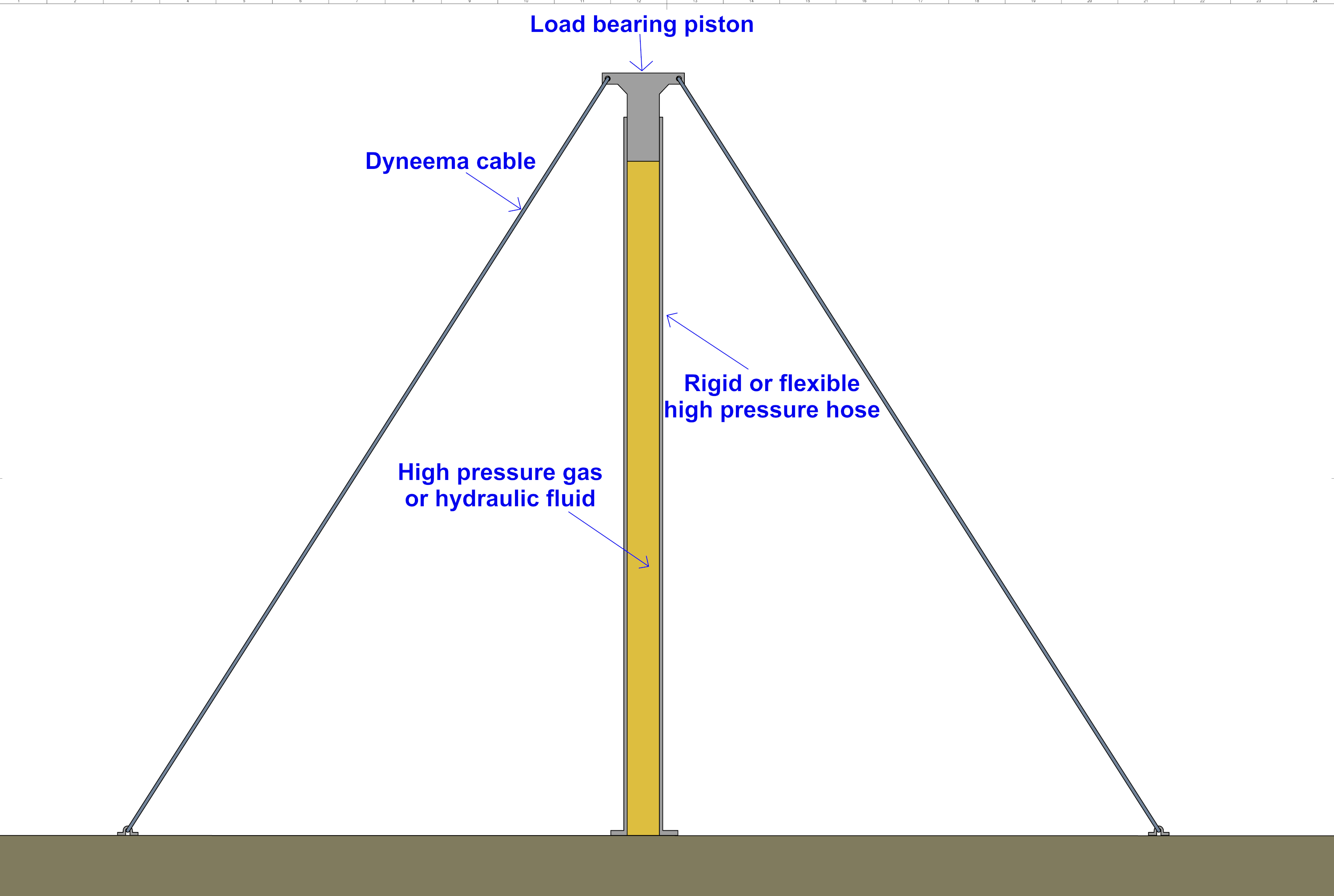
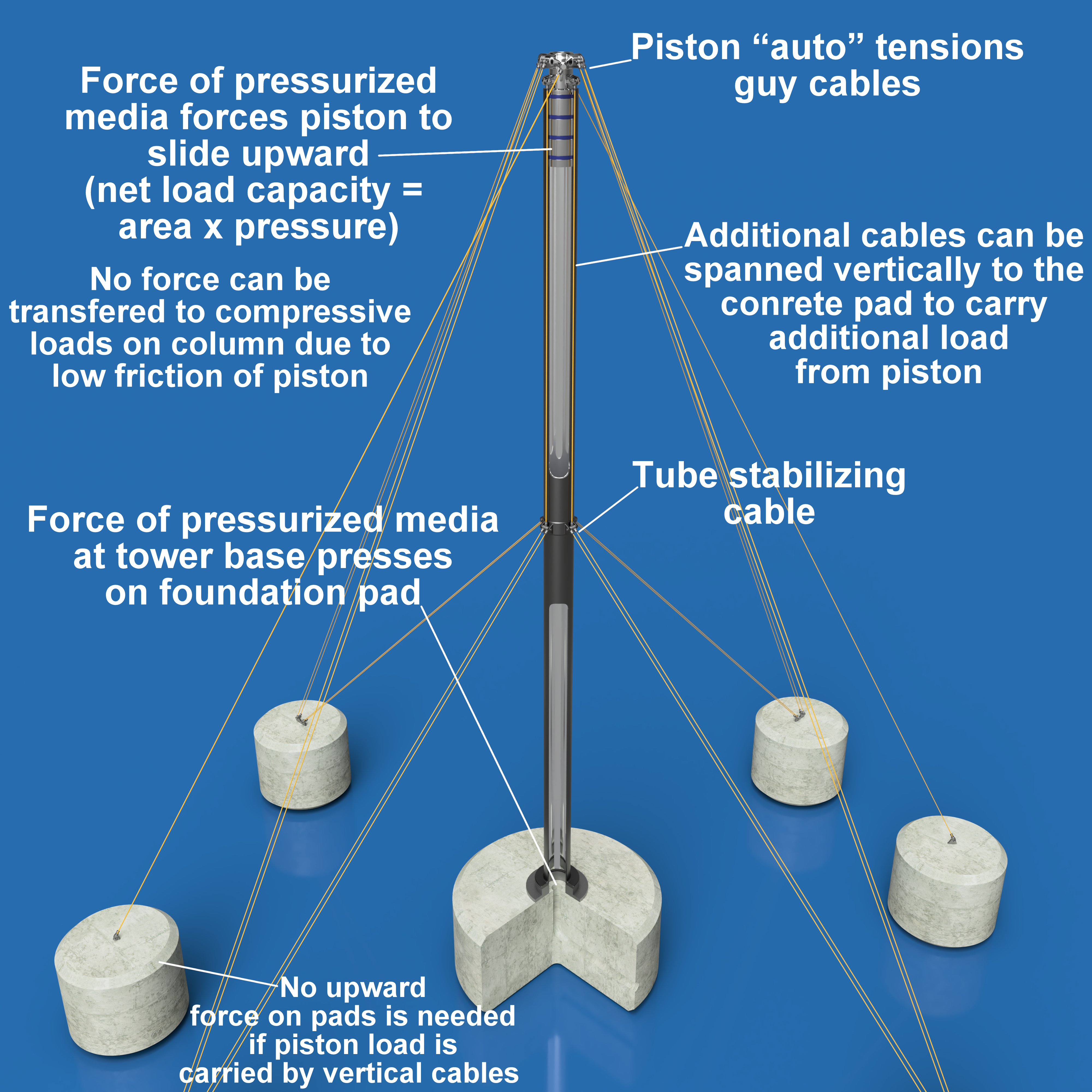
Pneumatic Guyed-Towers for Ultra-High Altitude Wind Turbines with Traction Drive Speed Increasers

A Revolution in Structural Engineering: The Rise of The Pure Tension Tower

Author: Christophe de Rivals-Mazères ,(Christophe de Rivals-Mazères Engineering), Residence Olbius Riquier Entree B, 11 Chemin du Martinet, Hyères-les-Palmiers , 83400 France. Contact: Mobile: +33 6 11 79 97 85

If you are interesting in developing this technology, please email at christophe@derivalsmazeres.com

Short introduction

The earth’s polar equator thermal gradient is a powerful heat engine that is a free and unlimited source of mechanical power. While there are challenges associated with its effective capture, it would be silly to ignore its vast potential just because we have more convenient sources of combustible fuels at the moment.

The boundary layer for wind traveling along the surface of the earth is up to 350 meters in height even on relatively smooth grass surfaces. This frictional resistance considerably reduces the available kinetic energy in the wind, constraining the potential power that existing wind turbines can extract. If a method existed to build wind turbines up to 350 meters tall, their power output would increase by 3.4x from a height of 50 meters (hub height for the Enercon E-44), without making any changes to the basic design and aerodynamics of the turbine, which has already reached a physical limit. Wind speed for a hypothetical location in Nebraska USA increases from 8.39 m/s at 50 m to 12.64 m/s at 350 meters as predicted by the power law using an exponent of 0.15-0.16 for grassy surfaces. Since the energy yield from wind is the cube of velocity, a 1.5 increase in wind speed translates into a much larger 3.4x increase in power. A near quadruplicating of the power density of a wind turbine is a very significant thing, allowing it to produce electricity for less than third of the current cost. Unfortunately, such an ultra-tall tower is simply not feasible with current engineering. Existing wind turbine towers make use of cantilevered masts, generating immense bending stress at their mounting point, requiring very thick steel construction, which results in high fabrication and material costs.
A better solution is desired so that the higher kinetic energy of higher altitude winds beyond the boundary layer can be tapped into economically.
Existing tall and slender structures are limited by the elastic deformation of the plastic material, primarily metal, used in their construction. Elastic deformation is a major constraint on the structural efficiency of metallic structures. An ideal structure would be constructed using only tension-loaded components, such as cables and pressure vessels, so that each structural element could be loaded just below the yield point without any structurally compromising deformation. To create a truly high-altitude structure, a means is sought whereupon the elastic deformation can occur only via the circumferential stretching of a cylinder which does not compromise the integrity of the tower. If the tower is made out of thin-wall metal but with a large diameter to evade Euler buckling, it will merely fail by crumpling or what’s called “flexural buckling”, so this is not a solution.
A classic way to increase the lateral stiffness of a tower is by fastening guy cables to transfer the lateral bending moment into vertical compression. Unfortunately, such a scheme does not increase the load capacity of a slender-column tower, since it simply discretizes the compression forces between the guy-cable mounting points. Guy cables therefore only impart an improvement in the stiffness of the tower, but they do not increase the load capacity, they are not in themselves a source of strength. A wind turbine is heavy and generates strong torsional loads, which cannot be born by a thin-wall tubular or lattice tower, regardless of whether it is laterally stabilized by guy cables. In order for an ultra-tall tower to work for a wind turbine, it must be very stiff and able to carry tens of tons of both static dead-weight and occasional gust loads which generate strong bending and subsequent compressive forces.
An elegant and perhaps genius solution is to employ the power of pneumatics to create a continuously pressurized gas cylinder acting as a tower to absorb the entirety of the compressive loads. Upon first examination, this idea appears obvious and seems to solve virtually every problem faced by the designer of a tall tower. Surprisingly, such an idea has never hitherto been proposed.

A the end of this cylinder a sliding piston would be placed to carry the loads acting on the tower. A method to seal the pressurized gas would be devised. In such a scheme, the lateral loads are transferred to compression along with any dead weight placed on the tower, which is then converted to hoop stress in the cylinder by pushing against the piston. But since the cylinder is filled with pressurized gas, the downward force is resisted by the force acting on the piston by the compressed air, which is at a steady-state pressure generating mild hoop stresses on the cylinder wall. A 750mm diameter constant diameter tube could generate 150 tons of force or equal load bearing capacity before displacement using only 4 MPa of gas pressure, requiring only 8mm in wall thickness to keep hoop stress under 160 MPa. This simply an unparalleled degree of structural efficiency, the ability of a light-weight thin-wall tube to carry 150 tons can only be realized using the power of pneumatics. The weight of this tube would only be 55 kg/m, or 19 tons for the entire tower! In this scheme, we have completely eliminated elastic deformation of the tower’s main structural member, and we are now able to generate a tower as tall as 350 meters using lightweight aluminum pipes filled with compressed air and stayed with cables connecting to the piston at the apex of the tower. The designer is no longer required to use thick gauge material to generate the required stiffness and strength to bear compressive loads since cables can produce all the needed stiffness by transferring their bending moment into the upwardly forced piston, and the walls of the cylinder can carry this compression force via gas pressure. This scheme is extraordinarily elegant since it optimizes the distribution of forces to minimize loading in ways that utilizes a plastic materials greatest asset: its strength in tension, while minimizing its greatest weakness: its susceptibility to deformation, itself a corollary of the very ductility we want for such a structure.

A series of cables can then be spanned vertically connecting intermediate guy cables to stabilize the thin-wall tube. A 0.75-1 meter diameter thin-wall aluminum cylinder/tube can be braced by cables every 25-40 meters, allowing an otherwise infinitely slender tubular column to be broken up into discrete rigid sections. Such a structure would be unique in the world of structures in that strictly speaking, it has no compression-loaded structural members other than its foundation. The guy cables experience only tension, and the thin-wall pressure-bearing column experiences circumferential and longitudinal tension. It should be noted that pressure vessels can be constructed out of materials with no intrinsic compressive strength or stiffness, such as aramid fiber (Kevlar) widely used to construct ultra-lightweight pressure vessels for space vehicles, so a pressure vessel is a solely tension-loaded structure. In order for such a structure to maintain long term structural integrity, redundant air compressors can be placed at the base of the tower to counter any leaks that could develop along the piston seal. A number of additional design considerations are discussed in a more extensive description that can be found in the following text.

Mazères Propulsion is the first company in the world to devise an entirely tension-loaded structure in the category of high-altitude guyed towers. When we mention “hydraulic or pneumatic” with reference to a tower, people assume it is some form of self-erecting mechanism, which is of course not new at all. We are not claiming novelty or that self-erection by itself is revolutionary, it is not, but we are claiming novelty to devising a method to build a structure who’s load capacity is unparalleled by conventional means. As long as the structure must bear weight with the material’s longitudinal stiffness, the tower is still limited like any slender structure: by buckling.

A “pressurized gas filled tubular guyed-tower” is a sui generis structure, in that it has no components other than a foundation, loaded in compression! Under the premise of ordinary structural engineering, much like one cannot design around the law of thermodynamics, it is strictly impossible to construct a conventional structure, that is one that relies on stiff members for load transfer, purely in tension. Such a scheme would be seen as violating basic mechanics, as it contains a discontinuous load path continuum. To truly “erase” compression, one must use hydrostatics. It will become immediately obvious upon further elucidation that a pressurized structure is extremely fascinating in this respect. Even in Buckminster Fuller’s famous “tensegrity”, there is always a lowly compression member, that might not catch the eye of the beholder, but that surely carries the tension of the string and transfers it right back into compression. One cannot escape the need for compression, because, by definition, compression is the reciprocal of tension, like a magnetic field is to an electric field or cold is to heat. A hydrostatic structure, being pressurized and loaded in hoop stress, does not actually possess any compression-loaded parts. One could say that the use of gas provides a “loophole” or a cheat that allows a violation of the conventional structural engineering logic that dictates that for every tension-loaded member, a member must ultimately bear compression in order to maintain a continuum. Since we can exclude the foundation pad as a compression member because it falls outside of the domain of the “above ground” structure, if we restrict ourselves to examining the portion of the structure that actually performs the critical load transfer, we find not a single component loaded in compression. Naturally, in light of this fascinating property, we have decided to name the technology a “pure tension tower”: (PTT). A pure tension tower in this case is merely a type of pure tension structure, the broader category refers to any structure, such as an inflatable dome or any pressurized structure that effectively transfer all their otherwise compressive forces isostatically to produce compression forces, but compression forces which do not necessary possess a load-path distribution parallel or coincident to the structure’s vertical plane. A pure tension tower thus produces compression, but only in the X and Y coordinate of the Cartesian plane. It therefor is able to violate this structural engineering dictum by cleverly orientating the compression in a manner that does not elastically deform the tower’s inherently slender shape. This term isostatic is important, because it perfectly describes the behavior of gas or liquid under pressure, they do not hold any preference, spreading their force homogenously across the entirety of the load-bearing surface. One cannot create points of force concentration or dispersal with a gas or liquid, it will find every crevice and impart its constant pressure towards it. The inherent tendency of pressurized fluids or liquids to produce uniform forces is termed Pascal’s law. The conclusion of this review is to the need to stress the role of the gas’s ability to impart isostatic force, this is the only conceivable way to generate a state of pure tension and what allows us to bypass this fundamentally structural axiom.

Full introduction

Mazères Propulsion has employed rudimentary logic according to first principles to the field of structural engineering to improve the structural efficiency of high-altitude structures in order to improve the energetic yield of wind generators. In order to do this, we designed a tower that could reach heights of 350 meters to increase the power output by 3.5 fold over a base height of 50 meters. In order to reduce the weight of this otherwise massively heavy tower, we have made use of a technology using internally pressurized thin-wall tower sections that are held in place laterally by tensioned guy cables. The weight of the wind turbine is born by the pressure inside these thin wall columns which push a piston that freely reciprocates within the cylindrical tower. The entire structure is made stiff and rigid by tightening guy cables to this piston at the top of the tower. The confluence of the higher wind speed and reduced mass needed to build the tower affords a marked reduction in the levelized cost of energy, since more energy is yielded from the same mass of material, yet even less weight is needed to construct it for the same power output. Further details of the technology are provided in the text below. Images and schematics which readily illustrate the working principle of the invention are provided below as well as priority patents which have alluded to similar concepts before. To summarize as simply as humanly possible, the tower uses the pressure of gas to exert force on a piston which bears the weight of the wind turbine as well as tensions a series of guy cables which prevents the structure from toppling over. The basic rationale is that thin and tall columns are suspectable to buckling due to elastic deformation, by pressurizing them, no force is exerted on the column as it merely serves as a way to keep the gas from escaping.

imafdge

Note this load-path and force distribution diagram. As weight is exerted on the piston, since there is zero physical contact between the floating piston and the tube’s wall, all force must be transferred to pressure in the liquid or gas, resulting in isostatic force transfer directly into hoop stress on the walls of the tower. This principle does not mean the structure has infinite load capacity, if more weight is placed on the piston than is tolerable as pressure in the tube, the tube will burst and the structure will then have zero load capacity. The structures “Achilles’ heel” is the need to eliminate 100% of the force or load transfer between the free-floating piston and pressure tube wall, this can be accomplished by a clever method explained in further detail. The invention is so simple it can be grasped by a child. But the diesel engine too is a simple invention (squeeze air to ignite viscous fuels), but it took a man of great intellect to invent it! Note that the image above was made with the assumption synthetic cables could be used prior to the realization that materials like Dyneema are subject to creep upon subject to a continuous load. The cables used would be ultra high strength steel cables from the tire industry. The invention effectively pertains to a column of compressed media that acts as loading bearing platform. As long as the fluid is contained and sealed within the cylindrical container, the structure has an “upward impulse” that keeps it aloft. Note that the article below is poorly organized as it was written very quickly and frequently edited with new information added. Mazères Propulsion is still a small company and therefore lacks a full-time editor. Some parts of this text are unrelated strictly to the technology in question and there are entire sections of text with no bearing to the technology in question. We are in the processing of cleaning up the article and removing these sections. The choice of a rather long and discursive article was not to bother the reader, but to highlight important points we believe were worth covering. Those who are not interested are encouraged to skim over and focus their attention on the technical schematics or short YouTube video. The article covers disparate topics such as manufacturing and material selection. The crux of the matter should be summarized in a manner as condensed as possible. This has been provided by a very brief and parsimonious introductory text above.

The image below is Mazères Propulsion “Pure Tension Tower” 750 kW 350-meter tall high power density wind generator. The turbine’s nacelle is constructed from a iso-grid aluminum truss-frame structure and clad with thin-gauge aluminum walls. The flat quad-pattern rectangular structure spanning outward is constructed from the same aluminum iso-grid, these members are used to fasten the vertical stabilizing guy cables, preventing the turbine’s nacelle from pivoting back and forth during strong winds. They also act as a torsion-prevention member, allowing lateral guy cables to prevent the nacelle from twisting along the tower during fierce winds. Mazères Propulsion‘ 750 kW turbine uses only 35,000 kg of aluminum to construct, costing only $100,000-$150,000 to manufacture using our novel iso-grid machined aluminum frame assembly. The LCOE of the turbine installed in Nebraska Sandhills would be a record breaking 0.10¢/kWh, 46 times cheaper than natural gas power generation. If the reader is not interested in reading our extremely detailed article, skip over and watch the video linked below to understand the working principle of the hydrostatic tower.

The novel dual-cable torsion prevention design. Two sets of quad-cables at 55 degree angles cancel even the slightest pivoting action of the cantilevered vertical offset of the turbine mounting platform. If the turbine experiences a powerful gust pushing to one side, the untethered mast will bend generating a sharp torsion force at the main guy cable mounting points shown above. The cable on the top left cable cannot prevent the mast from twisting in a clockwise direction, but the bottom right cable cancels this clockwise twisting, since the piston is vertically rigid. A clockwise rotation would require the bottom right cable to pivot the left, forcing the piston down. Torquing of the turbine relative to the main pressure-bearing tube is prevented by the eight cables, there is simply too much tension to allow but a slight degree of torquing.

Since lateral stiffness is of no use to the structure, the thickness of the tube need only be sufficient to prevent bending between guy-fasten points. There is no need for a bulky large diameter column if it is not subject to horizontal swaying motion from the mass at the top. A conventional cantilevered tower is a structural abomination, by concentrating all the swaying motion of the heavy nacelle at the bottom of the mounting flange, a massive stress concentration occurs requiring a huge over-use of material. A pure tension tower is unparalleled in its structural efficiency due to a harmonious load path distribution and the widespread exploitation of isostatic loading.

Below is a video showing an example of a small scaled prototype of the fundamental principle of a compressed medium column.

hydrostatic

Further description

The basic working principle of the technology is the use of a pressurized medium, a gas in our case, to continuously press upon a receiving piston that is used to carry both structural and dynamic loads and generate tension by pulling on ground-mounted high taught guy cables. A slender cylindrical column spans the height of the tower and is laterally stabilized by guy cables, this tower carries in it the pressurized fluid that is prevented from expanding at its base, but allowed to expand on a free-floating piston. This piston, when experiencing the isostatic force of the fluid or gas, has the urge to move upward, increasing its height. If cables are placed to restrain this piston from moving along the Z coordinate, tension is naturally generated as long as the cable’s mounting pads are firmly seated in the ground. Once tension is generated, stiffness is available that can be used to generate a laterally stable structure. The structure can be simply thought of as an incompressible column braced by tensioned cables, in that there is no fundamental difference between a solid concrete column and one whose equivalent incompressibility derives from pressurized media. Although this accuracy of this statement from a strictly mechanics perspective is questionable. Since the pressure column expands up to its elastic modulus upon being filled, and any force on the piston that does not exceed the net pressure load acting beneath it, will result in zero downward deflection. All structures require both tension and compression-loaded members, this structure simply uses pressure to generate compression and cables for tension.

A hydrostatic tower, hydraulic column, pneumatic column, isostatic structure, pressure-filled tubular load-bearing member, pressurized cylinder tower, defined hereinafter as a pure tension tower, works by imparting molecular energy from a compressed gas or liquid onto a piston and using that energy to bear loads, through the use of a friction-free piston free-floating above the pressurized media in a sealed container. Since the walls of the sealed container are unable to expand beyond a slight initial elastic deformation, the pressurized gas takes the path of least resistance and travels upwards to the free-floating piston and down-ward on the same piston but installed on a concrete footing. Since the free-floating piston has no resistance, it is freely pressed by the fluid and is subject to the sum of the force of the pressurized media. The force of the free-floating piston at the top of the tower can then be used to carry nearly unlimited loads without transferring these loads to the containment pressure tube. This simple but powerful statement is critical to understand the working principle underlying this invention. If the piston were to have friction between it and the cylinder wall, any load placed on the piston would be transferred as a downward compressive force which could buckle the thin walled column. 

The critical fact to understand is that once fully pressurized, the cylinder is unable to move down unless a force greater than the force acting upon it is produced, in other words, the load would need to exceed the pressure inside the column for the tower to sag under a load. Since the sealing mechanism (discussed in further detail further along the page), is unable to transfer even a few kg of force to the walls of the tube, the load is always and everywhere borne solely by the pressure media. In short, the structure derives its load-bearing capacity by using a portion of the upward force produced that would otherwise have to be carried by the restraining cables by placing and carrying a weight on the piston. If a load that comes very close to the hydrostatic force is placed on the piston, the piston is able to reciprocate by slowly compressing the medium below, but by definition, a force cannot move the piston unless its sum is greater than the pressure acting on it. Since the target application for this novel type of tower is wind energy, the piston would then carry the dead weight of the nacelle, blades, plus any lateral exogenous forces resulting from static wind pressure acting on the turbine blades, nacelle, counterweight, in addition to the lateral loads acting on the tube. Using highly intuitive Newtonian mechanics, it can be readily illustrated that the structure’s load-bearing capacity is thus equal to the area times the pressure using the formula: pressure equals force divided by area written as: P = F/A. There is sometimes confusion about the nature of force produced by compressible gases, since conventional pneumatic structures (inflatable domes) are viewed as “spongy” and infinitely flexible, some have difficulty understanding how a pneumatic structure can possibly possess rigidity. The answer is that to compress a gas, a given amount of energy or force is needed, and the force is proportional to the pressure, thus as the intermolecular distance of the gas molecules decreases, electrostatic repulsion increases, and proportionally more energy is required to displace them. So while it is true that pneumatic structures are “spongy”, this is only the case at very low pressures where the structure’s loads can often momentarily exceed the outward force from the gas, serving to temporarily compress the gases inside the containment canvas. While it is correct to state that gases are theoretically almost infinitely compressible (in reality they are not once a high pressure is reached), and if enough force is available, they can be continuously squeezed until the gases would eventually turn to a solid. A gas effectively behaves as a solid if its pressure is well above the surrounding forces. A compressed is gas thus a wall of incompressibility provided there is less force applied than the gas contains from its compression. 

The pure tension tower structure works by ensuring that the structure’s payload is always less than the force needed to compress the gas, even at peak loading regimes such as during freak storms. As already stated, a load cannot move a compressible medium if the compressible media contains within it an energy level that yields a force that exceeds the force applied, no matter how compressible the medium is. Gas is highly compressible, yet one cannot stop a pneumatic cylinder from retracting with their hand nor an internal combustion deriving its torque from expanding hot nitrogen gas, even though the gas residing within these devices can be squeezed. It is important to realize that all heat engines are “pneumatic” in principle insofar that they rely on the force of gases under pressure to produce work. A pure tension tower is thus a stationary pneumatic engine, rather than extracting work by creating motion, it extracts a static or idle force to counter a lesser static load. In the pure tension tower, the pressure bearing component is constructed from a cylindrical pipe that spans the height of the structure, which can approach 350 meters. The pressure-bearing tube, while not subject to the gravimetric load of the nacelle, is nonetheless still subject to the static force of the wind which causes it to bend. This bending motion is prevented from occurring with the guy wires that ultimately transfer this lateral wind load onto the piston which is prevented from displacing down by the fluid pressure acting on it, thereby allowing the lateral guy wires to prevent any deflection of the pressure column. The upward force of the piston allows the column to be tensioned thereby reducing the compressive loads it must withstand to zero. In a classic guyed tower, the tower section wants to bend from the force of the wind, and while the guy cables may prevent this, this lateral force is simply transferred or converted directly into compressive loading. A classic guy tower thus fails in both compression and buckling, since by definition any force withstood successfully by the guy cables is always transferred to downward force on the tower since the guy cable can only pivot and cannot stretch. As the tower wants to bend, the cables must pivot since they cannot stretch, as a result, the only way for lateral movement to occur is by shortening the tower, that is for the tower to sag and droop under a load, even though the direction of this load is not vertical. This places very strong compressive loads on the lattice structure of the conventional guyed tower. In the pressurized media tower, this is completely obviated by running a series of cables vertically from the piston down to the intermediate tube stabilizing guy cables which are placed every 15-25 meters depending on the thickness of the tube. The diameter of the tube is determined by the maximum expected wind load, for a 750mm diameter tube, a wind speed of 67 meters per second would cause a deflection of approximately 4 to 5 mm for a span of 25 meters. In a guyed tower, regardless of whether it is a hydrostatic one or a classic one, the tower sections are treated as discrete members rigidly connected at their fastening points which correspond to the mooring points of the intermediate guying anchors. With the pure tension tower, as the tube wants to bend from the wind, the lateral guy prevents it by attempting to compress the tube, but rather than this compressive load being transferred to the tube, it is transferred to the piston by the vertical cables. The tube is encased within a series of helicopter swashplate-like brackets that are not rigidly attached to the tube, allowing the tube to move ever so slightly within them by pressing against a rubber diaphragm. These swashplate-like brackets fasten to the four vertical cables spanning the height of the tower and then fasten to the lateral cables. Since the lateral cables are rigidly connected to the vertical cables which connect to the top-piston, pivoting action is canceled maintaining a straight and rigid pressure column regardless of height. Of course there are limits to the allowable height due to the accumulation of peak wind gusts on the tubular tower section. Therefore, one can say that the tube itself is simply standing there virtually “idle”, indifferent to the prevailing loading regime, needing only to perform its job as a pressure container, with the entirety of the exogenous structural loads carried by the piston which is then carried by the force of the “desirous-to-expand” fluid, and ultimately, all of which is born by the tensioned cables and transferred to the foundation on the ground. It can be said that a pressurized media tower’s raison d’etre is its unique and elegant ability to entirely bypass classical Euler buckling, flexural buckling, or compressive failure no matter how tall, slender, and thin the column is. As long as the lateral guy cables are placed frequently enough to minimize column bending during fierce winds, the structure is unable to move unless the loads exceed the yield strength of the steel cables. In fact, since the 1-meter pressure column spans around 20-25 meters between guy mounts, it therefore actually features a lower slenderness ratio than most untethered wind turbine towers! The tower section is in fact far more rigid since it functions as a discretized member at all times. In other words, the tower is not 350 meters, but rather 25 meters or whatever is chosen as the guy interval, which means its actual slenderness ratio is actually very low. Conventional wind turbine towers or masts are rather slender cantilevered structures which are free to bend and sway often quite severely in the wind. This can potentially although rarely cause resonance if the blade rotational speed syncs in phase with the cantilevered tower’s natural frequency. A pure tension tower is so immensely stiffer than any cantilevered tower that it is not even remotely comparable. At first appearance, a guyed tower appears so slender and skinny that it almost defies structural engineering, but it bears repeating that a pure tension tower is never treated as a singular member, but rather a multitude of stacked and rigidly connected discretized members that span the height of the tower in increments between guy fasten points. Think of each lateral guy mount as a foundation, no different than a foundation pad holding a building’s column in place, the only difference is rather than the connection being facilitated by the torsional resistance of the footings, it is withstood by maintaining a maximum load less than the force needed to stretch the restraining cable. Each cable is tensioned to the point that the average force acting on the column is far less than what is needed for the cable to plastically elongate let alone yield.

The essential point to understand is that the pure tension tower works by exploiting the properties of the plastic column material by transferring a directional compressive load into uniform hoop stress or internal pressure, distributed evenly along the interior surface of the cylindrical tubular containment structure, which remains loaded only in tension the entire time, regardless of the force acting on the piston. The pure tension tower thus converts compressive load into tension, which is a unique feat among structural systems. Most structures, including structures that use tension-loaded cables such as cable-stayed bridges, still nonetheless exploit the compressive load capacity of the concrete columns. In fact, no structure in existence can operate without at least one member being compressively loaded, the famous “tensegrity comes to mind.

s549125031131435850_p184_i1_w1838

The tensegrity, coined by Buckminster Fuller, is not really that genius after all, since it still places compression on the upward facing wooden strut visible in the image above. The pure tension tower in contrast is truly a compression free structure. The word “tensegrity” is therefore a misnomer because the structure is equally compressively load as it is tension loaded.

A pure tension tower does not use a single compressively loaded structural member! In fact, if one excludes the footing, it has none. As long as the piston generates zero friction between itself and the cylinder around it, it is physically impossible to transfer any compressive load to the column, unless the lubricating medium between the piston surface and tube were to seize or solidify for some reason. Only the viscous friction within the thin layer of oil between the piston and cylinder can transfer loads from the piston to the tubular structure, but this force is negligible. Since all plastic materials (including metals) will not elastically deform prior to yielding in a structurally compromising manner in tension, a hydrostatic structure is able to increase the structural efficiency of the load-bearing members by an enormous factor. The technology is discussed in much greater detail below including how a truly friction-free piston is designed. In short, a friction free piston merely continuously routes a highly viscous oil between itself and the cylinder wall, preventing any pressure from pushing a piston ring against the cylinder and generating friction.

We are forced to mention that a pure tension tower as a structure has no inherent relationship with wind generators. Wind generators are a wholly disparate field of engineering with their own unique, and arguably more challenging design exigencies. The pure tension structure technology is itself a lone branch of structural engineering that can barely be encompassed within the category of pneumatic structures. Since it does not obey the peculiar characteristics of conventional pneumatic structures (infinite flexibility), it cannot be fully placed in this already amorphous category. Consequently, for the foreseeable future, the technology will have a difficult time being assigned a specific category of any widespread name recognition. The only reason there is an extensive overview of wind turbine technology is due to the fact that there is very little use for a pure tension tower other than cellular and radio masts, but these structures do not need much load-bearing capacity and hence can sufficiently with lattice structures, this is why this form of structure has not yet been invented

frame 2-1

Schematic of the nacelle stabilizing structure. Since the column produces a constant upward pushing force, torsional forces are withstood by transferring them into compressive forces across four laterally projecting pressurized columns, the same pressurized column system as the main load bearing tower. Any torsional force produced is canceled by the pivoting gyro placed at the piston’s center to prevent the piston from rubbing against the cylinder wall and generating friction.

Small reference model of a short pure tension tower. Note that a pure tension tower is “height-invariant” in that it is a discretized tower, not a singular cantilevered tower. By breaking up the tower between guy fasten points, we can treat it as a series of stacked small towers, which is why they can boast such high slenderness ratios which defy the imagination yet possess an even stiffer facility than any cantilevered tower.

untitled.57

The basic schematic below of the pure tension tower. The load-bearing piston, which carries all the load of the payload placed atop the tower, plus any wind force on the tube, cables, or payload, is never in any way adhered or adherable to the tube’s wall, so the pressure column is an unloaded component excluding the internal pressure and wind loads. The critical failure mode of the thin wall pressure column is flexural buckling or crumpling, no such event can occur since the tube is constantly tensioned as it floats on the bottom-mount piston on the foundation pad. Since pressure is a uniform force, pressure cannot cause a directional movement of the member unless there is an unequal surface area distribution. In other words, pressure acts to move bodies only if they are not submersed in the media, otherwise, the force of the pressure on the other side of the surface cancels it, it then becomes an “atmosphere”. The pure tension tower thus uses the weight of the dead-load to cancel the upward force of the pressure below a certain margin.

A technical schematic of the basic pressurized media tower components.

Fullscreen capture 7112022 20937 AM

Before we go into more detail on the design, workings, and engineering factors that go into the pure tension tower, it is necessary to provide an overview of the motivation behind the technology’s development. Since a pure tension tower have a single point of failure, their use makes the most sense for cost-sensitive applications where the safety of humans is not dependent on the structure’s reliability. Despite the structure’s stellar mass to payload ratio (structural efficiency), like all technologies, it is not perfect. It possesses several weak points, an “Achilles heel”, if you will. This is unavoidable and comes with any complex system. An airplane cannot fly without an engine or a working hydraulic system, nor can an aerial tramway function without effective breaks and strong cable attachment points. The so called O-ring theory effectively states that regardless of how over-engineered the machine might be, there will always be failure modes unreceptive to over-engineering that ultimately limit how much one can engineer in redundancy. The principal weakness for the pure tension tower is the ability for a leak to eventuate in complete structural failure. Since without internal pressure, the structure has no load-bearing capacity whatsoever, a major leak caused by a failure in the sealing mechanism or a puncture in the tube walls will inevitably result in the structure’s complete collapse. Thankfully, engineering and material selection can mitigate this and make it rare enough to be accepted as a non-human carrying structure. It should be noted that we are by no means the only technology that is dependent on the absence of leaks for system integrity, a number of high-pressure systems are found in engineering where severe leaks can result in major failure or hazard, notable in cases where toxic or flammable compounds are being stored such as in oil refineries and olefin polymerization plants. Even though hydraulic and pneumatic sealing mechanisms (discussed extensively further down), can be made extremely reliable, and while they could find immense use for civilian structures and building construction, it is anticipated the PTT’s prime application will be in wind energy, therefore a relatively extensive discussion of the salient facts pertaining to the energy landscape is performed.

Motivation behind the invention

It has become almost trite to say energy is by far the most valuable asset after human capital for a nation. The entirety of modern industrial civilization is predicated on the continued flow of power dense streams of calorific compounds, without which no modern technological society could sustain itself for more than mere months. Unfortunately, the planet contains only small quantities of highly concentrated energy, most of the energy available on earth is in a diffuse form, highly dispersed across its surface as downstream solar energy. In this vein, it must be stated that there is presently no evidence of a genuine “shortage” of energy, there are massive supplies of coal, natural gas and petroleum readily extracted with century-old technology that will likely be available for centuries to come. In spite of this rather auspicious predicament, headlines are chocked with news stories of an impending “energy crisis” about to send industrial civilization back to the stone age. One has only to make a little effort and search historical newspapers, books, and articles, of which there is no scarcity, for predictions of looming droughts of oil or virtually every other precious resource. There is very little geological and technological evidence and veracity behind any of these sensational claims, historical or modern. Those who claim energy is in short supply are conflating risk premiums with supply-driven price escalation. Risk premiums are often ignored in the energy debate, with consumers conflating genuine scarcity with monopolistic supplier behavior. A perfect illustration of this phenomenon is the recent escalation in the price of natural gas in Europe. Natural gas in Russia is more abundant and cheaper to produce than ever, after all, drilling technologies, pipelines, and storage continues to improve in efficiency and cost effectiveness. But instead, unwise politicians imposed sanctions which resulted in retaliatory behavior on the part of Russia, driving the price of an otherwise incredibly cheap resource to absurd highs. In light of these facts, there is still nonetheless tremendous demand for energy, often expected to be made available at a market price below what is currently available. In this regard, wind has a number of attributes. Wind is a manifestation of the angle of incidence of solar insolation increasing with distance from the equator, creating permanently frozen zones called the poles. The past 50 million years, since the Eocene thermal maximum, has witnessed tremendous cooling imputable to declining atmospheric density, resulting in a sharper pole-equator thermal gradient, generating more powerful winds. When the earth’s atmosphere is thicker, as it was during the Mesozoic, more of the earth’s energy budget was derived from adiabatic heating of the atmosphere through the gravito-thermal effect, causing a more uniform temperature distribution. As the atmosphere has thinned, cooling has been the norm. The earth is expected to continue to cool until its atmosphere is eventually stripped away when its internal dynamo shuts down as the core cools and solidifies. But this represents the long term cause of climate variation, the short terms temporal variations we have witnessed are imputable almost exclusively to a complex interplay between sunspot activity, cosmic ray flux, and cloud formation, called “cosmoclimatology”, coined by Henrik Svensmark who first proposed the mechanism.

RomanMedievdalNow2

The current climate on earth is in a warming cycle, caused by a reduction in cosmic ray activity due to a high sunspot count which started at the end of the “little ice age” in the mid 19th century. When the sun’s volatile magnetic fields are dormant, more energetic particles escape the photosphere and make their way to earth. When they strike the atmosphere, they ionize aerosols such as sulfuric acid and generate cloud condensation nucleons, which act as seeds for clouds to form, blocking more of the visible and ultraviolet spectrum from striking the surface of the earth. The concentration of beryllium 10, chlorine-36, or carbon-14 serve as proxies for historical cosmic ray intensity and subsequent sunspot activity. There is a major misconception that carbon dioxide acts as a “climate knob”, this is one the greatest myths of the current era. The current “modern warm period” is anticipated to reverse some time this century, sending temperatures falling back to substantially below the current “modern warm period”. This will create a sharper polar-equator thermal gradient and increase global wind speeds, making wind energy a very attractive energy source. When sunspot activity begins to decrease, temperatures will likely a full degree in a century, reversing the entire 0.8 degree of modern warming, causing wind speeds to increase by at least 10% globally. Wind power is the cube of velocity, which means a 10% increase generates a 35% increase in extractable energy. Solar irradiance varies only around two-fold between a very sunny region such as the Sahara Desert and a low irradiance climate such as England and Whales. In contrast, wind speeds may very from three meters per second in the tropics to 15 meters per second in the Ice sheets of Greenland, a difference of 5 times. This means wind is 2.5 times more variable than solar energy, which has a unique advantage for power generation. While the average power density of wind and solar energy is quite close, the potential to harvest the extreme ends of the distribution is greater with wind, this is a unique way to exploit a statistical phenomena manifested as polymorphous energy fluxes. Two phenomena that are normally distributed along a Gaussian curve with the same mean can produce different extreme values with a difference in only their standard deviation.

Returning to the subject of energy, while we have a number of options on the table, not all are as easily deployed. The caloric value from the heat of decaying radioisotopes and residual mantle heat is extremely weak at depths available to present drilling technology, placing a cap on the availability of geothermal energy. The highly concentrated energy, and the one we rely on for the bulk of our caloric needs, is principally in the form of gaseous and solid carbon-hydrogen compounds, with oils forming only a small percentage of the total array of carbonaceous hydrogen bonding compounds. Of all the calorie-emitting compounds in the crust, virtually all of them are in the form of carbon and hydrogen, there are no other heat-emitting molecules that we have access to for energy, silicon or other metal hydrides have not been found in the crust. While most earth abundant metals, iron, aluminum and magnesium, in their reduced form can be burned to liberate considerable heat, they exist only in their oxidized states, and hence do not contain any net surplus of energy. It needs to be stress that hydrocarbons are the only “pre-reduced” compounds we know of, virtually everything around is is already highly oxidized, hydrogen are thus quite precious and outright anomalous. Hydrocarbons are thus a unique case of highly reduced compounds that have remained free from the ravages of our oxidizing atmosphere. Russian physicist Vladimir Larin proposed a unique theory that the mantle and core is comprised principally of metallic hydrides which over time degas into the atmosphere, accounting for the occurrence of hydrogen in the exosphere and potentially even abiotic hydrocarbons. Abiotic hydrocarbons may be quite dispersed in the crystalline crust, but remain inaccessible due to the high cost of drilling. Larin proposed a very novel theory in the 1980s and went on to write a book titled: “Hydridic Earth: The New Geology of Our Primordially Hydrogen Rich Planet”. A documentary was made about the theory in Soviet Russia that can be viewed on Youtube.

Fullscreen capture 8152022 103034 PM.bmp

Larin’s basic theory was during earth’s formation, the protoplanetary disk that emerged after the after the collapse of the molecular cloud sent a stream of particles particles toward its outer edge that eventually formed into the earth. Elements with low ionization potentials, low voltages needed to to ionize, were captured and retained by the sun’s magnetic field, while elements with high potentials, hydrogen for example, which requires a high 13 electron-volts to ionize, could escape the sun’s magnetic field and make their way to earth. His thesis is corroborated by the correlation between the ionization potential of the elements and their distribution on earth. Larin’s theory predicts earth contains 1500 times more hydrogen than is commonly assumed, 4.5% vs 0.003% by mass. Larin’s theory has important implications for the abiogenic hydrocarbon origin theory since we now have a mechanism that can produce a continuous supply of hydrogen. Larin believes that rather than pure metallic iron or nickel in the core and mantle, there exists considerable quantities of hydridic compounds, such as nickel hydride or iron hydride. The polymerization of hydrocarbons takes place in the temperature range 600-1500°C and at a pressure range of 20-70 kbar. These conditions prevail deep in the Earth at depths of 70-250 km beyond the lithosphere and well into the asthenosphere. The carbon found in the carbonate rocks (Calcium carbonate) fuses with H2O in small crevices and slowly peculates to above under high pressure. These incredible pressures allow the formation of longer chain hydrocarbons like oil, while at more moderate conditions, simple molecules like methane and butane form. In the Russian geological community, this process is called “deep abiogenic”. A strong reason to believe in the unorthodox abiogenic theory is that fossils have not been at depths greater than 16,000 feet, while natural gas is drilled as deep as 39,000 feet. The well in Eastern Russia in the region of Sakhalin known as Z-44 Chayvo, reaches a depth of 40,000 ft (12 km) into the ground. How decomposing organic matter could have reached such a depth is presently unknown, subduction is likely not a satisfactory explanation. Secondly, no fossil has been found at these depths. L. Fletcher Prouty, a general and business executive, became a staunch proponent of the abiogenic theory. There have been numerous experiences in Russia where an oil or gas well is depleted, left to sit for a few years, and then is refilled somehow. With that said, even if oil is a renewable resource, that does not mean it cannot be depleted. It’s probable that the natural production rate of hydrocarbons in the asthenosphere is substantially below the rate of extant human consumption. Therefore, it makes little difference is hydrocarbons are a fossil or not, they will be depleted, it is inexorable. Lastly, biotic molecules, organic carbon-hydrogen oxygen molecules like β-Carotene, Vitamin D etc are highly oxidized with very low chemical potential. A large sum of energy was needed to reduce them to the highly reduced state of energetic hydrocarbons of high chemical potential. This energy could only have come from the mantle from the buried hydrides. Vladimir Larin estimates as much as 500 billion tons of hydrogen are being degassed into the atmosphere, which explains the high concentration of hydrogen in the exosphere. If only a small fraction of this degassed hydrogen picks up a carbon atom from a carbon bearing rock this is enough to generate all the hydrocarbons we see today. Since carbon has a lower ionization potential, more of it would have stayed in the protoplanetary sun than could have reached earth, so this explains the relative scarcity of carbon on earth. Larin does not estimate the carbon content of his earth model as any higher than the conventional estimate. Larin’s theory predicts that the earth must be expanding since its density must decrease as a consequence of the hydrogen degassing.

Carbon is found in the upper crust at a concentration of roughly 0.02%, only 2.38 times higher than the concentration of nickel, an expensive metal, and 4.75 times less abundant than manganese, a moderately expensive industrial metal. Carbon is also rarer than strontium and barium, hardly elements abundant enough to burn ad libitum. Most of the carbon in the crust is in the form of carbonate rock, limestone, and dolomite, highly oxidized states with no caloric value to speak of. It’s estimated that of all the organic carbon on earth, only 0.01% is in the form of hydrocarbons within the sedimentary rocks. While the theoretical quantity of hydrocarbon is massive and represents thousands of years of present consumption, the tiny fraction that is amenable to extraction renders an initial huge number a far more meager one. Man consumes around 4.5 billion tons of oil annually, 3.8 trillion cubic meters (2.6 billion tons) of natural gas (methane), and 8.6 billion tons of coal, for a total of nearly 16 billion tons of hydrocarbon annually, or 1000 years of present consumption if we take the estimate of 2 × 10^13 tons of hydrocarbon as the theoretical reserve. Most of the crustal carbon is in an oxidized state bound up with oxygen, offering no energetic value to speak of. A small fraction of this 0.02% carbon concentration is in the form of energetic and highly reduced molecules: the valuable carbon hydrides that man profusely mines for. Prosini et al estimates the total reserves of hydrocarbon to be nineteen quadrillion, but of course, these estimates are silly and for intellectual curiosity only, since current drilling technology limitations makes most of this theoretical reverse inaccessible. The estimated reserves of methane hydrates in the arctic seabed are immense, numbering thousands of years, no present extraction scheme has been proposed. The U.S. Geological Survey estimates that methane hydrates could contain between 10,000 trillion cubic feet to more than 100,000 trillion cubic feet of “natural gas”, an American industry term for methane and ethane. The world uses 30 trillion cubic feet annually, thus, the theoretical reserves assuming 100% extraction efficacy (far from possible) would amount to more than 1600 years. In a book by Michael D. Max, Arthur H. Johnson, William P. Dillon titled: “Natural Gas Hydrate: Arctic Ocean Deepwater Resource Potential”, they estimate the total global resource potential for high-grade natural gas hydrate sands may hold up to 43,300 trillion cubic feet of which 50% is technically recoverable. Other estimates place the number at 1.5 x 10^16 m3 (Makogon et al., 2007) to 3×10^18 m3. In contrast, total reserve estimates for coalbed methane is 9,000 TCF, shale gas of 16,000 TCF, and tight gas of 7,400 TCF. Turbidite-related sands of the Terrebonne Basin have been estimated to possess a natural gas density of 1.183 × 10⁹ m3/km2 while so-called delineated sand reservoirs are thought to be around 0.32 × 10⁹ m3/km2. Max, M. D., Johnson, A. H., & Dillon, W. P. (2013). Natural Gas Hydrate – Arctic Ocean Deepwater Resource Potential. The International Energy Agency (IEA) estimates that if efficient methods and processes are developed, natural gas produced from methane hydrates will cost between $4.70 and $8.60/MBTU. This places the generation cost at 4¢/kWh.

While at the present moment there is ample hydrocarbon available, one must not forget that hydrocarbons are by no means inexpensive anymore, and many small scale users of energy would greatly benefit from a lower cost non-consuming energy source. This is not because technically illiterate politicians call for it, but because the LCOE from photovoltaic and existing wind turbines is often substantially below combusting a hydrocarbon at retail value in a heat engine. While it is true “renewables” (natural harvesters) are “unreliable” and geographically limited, there is almost invariably a trade-off in any physical system between two extremes. In this case, the two extremes are energy density and diffusiveness. It is logical to assume diffusiveness should be inversely related to energy density, since the bulk of energy is in a diffuse state while concentrated states occur rarely due to eventual entropy, oxidation, and degradation. It therefore follows that if we choose abundance we should sacrifice power density. An extreme case study is nuclear, the most power dense energy source presently known, but one which is reliant on an exceedingly scarce element. If an input of fuel is not required, certainly, we must accept some disadvantages. Critics of alternative energy often adduce the cost advantage of natural gas or coal over photovoltaic or wind generators, but the reality is quite a bit more complex and case-specific, especially when grid connection and the non-baseload nature of the energy are taken into account.

If we take the current spot price of natural gas, which in the U.S hovers between $6-8/million MBTU at the time of this writing, it becomes immediately obvious that the notion that “natural gas” is a “cheap” source of power is largely relative. There are 293 kWh in a million BTU, so the price of natural gas on a raw heat basis is 2.3¢/kWh. Since the average efficiency of a dual-fuel gas fueled diesel engine with pilot fuel injection is 40%, a medium-sized gas turbine is 35%, and a spark ignited Otto cycle gaseous reciprocating generator is only 30%, the cost per kWh electrical is around 2.5 to three times more than the raw value of the material. While very large industrial gas turbines such as the GE-7HA can approach 60% efficiency, this technology is not accessible to the small user, our target customer is the mid-size consumer of industrial energy, so we must remain scale conscious. Thermal powerplants are highly scale-dependent due to heat transfer and aerodynamic reasons. Since gas turbines are rarely above 30% efficient at the sub-megawatt scale, we can use a pilot-injected diesel engine instead for our comparison. Such an engine approaches 40% brake thermal efficiency, so if our natural gas price is $7/MBTU, we generate 117 kW of net brake power, since our generator is 97% efficient, we are left with 113.68 kWh, or an LCOE of 6.15¢/kWh. This number might seem like a low number for consumers who are price-gouged and must shell out over 30¢/kWh in Europe, but this price is hardly cheap compared to hydropower or nuclear fission, let alone contemporary photovoltaic which can reach 1.5¢/kWh in deserts. Obviously, we would be silly to use the price of European natural gas, which is artificially high compared to production costs due to a risk premium. In Russia in 2021, natural gas (methane) was sold to businesses and consumers at a price $0.009 and $0.01/kWh respectively, assuming 40% conversion efficiency, a bitcoin miner in Russia could realistically access power for 2.5¢/kWh, but not much less.

Of course, we could have cited the efficiency numbers of a General Electric 7HA, but this turbine is only available to grid operators since it costs over $50 million. Mazères Propulsion has been interested in developing the concept of slightly smaller scale systems, more accessible to small-scale players in need of affordable energy, that is we are interested in overturning the paradigm of grid dependence, where public utility monopolies sell overpriced energy to consumers with no alternative options. Mazères Propulsion has also been actively developing a very low cost power generator for bitcoin mining, so far no such technology exists except for hydropower dams, which are inaccessible to individual miners. In the later part of this text, a discussion on the possible LCOE regimes attainable is provided. It is possible for power as cheap as 0.083¢/kWh (yes 0.083¢!) is attainable in high wind regimes.

In the case of coal, the energetic cost-effectiveness is typically inferior to natural gas (methane) since the thermodynamic efficiency of the Rankine generator is poorer than the Brayton gas turbine. Newcastle coal futures have historically traded at $100-150/ton, historically speaking referring to the past decade. In recent months, coal futures have jumped to over $400/ton due to a convergence of circumstances, but principally growing electricity demand caused by increasing air conditioning demand and rebounding industrial production in China after Covid lockdowns. Unfortunately with coal, highly efficient Brayton and Diesel cycles cannot be exploited, leaving marginally efficient Rankine cycles as the only option. Most steam turbines are under 30% efficient unless in the supercritical class, where CAPEX becomes an increasingly dominant factor. Additionally, the cost of the steam turbine and boiler per kW is far higher than a gas turbine due to its much lower power density, hence a greater material intensity.

Since carbon comprises 90% of typical anthracite coal by mass and carbon possesses a heat of formation of 32 MJ/kg, we are left with 8.86 kWh/kg. At €150/ton, the levelized generation cost is therefore 5.6¢ excluding boiler, turbine, and condenser CAPEX. Since coal is not always 90% carbon, a more conservative estimate of 20 MJ/kg is used, most “steam” coals possess between 20 and 25 MJ/kg, or just under 7 kWh, yielding an LCOE of 7.5¢ at $150 per ton with a 30% efficient turbine. The reason that “steam coals” or any coal in reality possesses a lower heating value than the theoretical heat of formation of carbon alone is due to the presence of moisture in the coal, sapping the energy during its evaporation. Steam turbine price estimates can be sourced from online marketplaces like Alibaba, which are usually very accurate estimates of real-world wholesale market prices. Dongturbo Electric Ltd retails a 1000 kW condensing steam turbine for around $250,000-300,000. These medium-sized condensing turbines consume between 5-6 kg of steam per kWh. The inlet pressure is 2.1 MPa and the inlet temperature is 300°C. The CAPEX of the attendant coal boiler is approximately $50,000. Since we are comparing to a wind turbine, we can exclude the cost of the synchronous generator, since a steam turbine would require a synchronous generator as well. The cost per kW for a small scale 1000 kW coal powerplant so far is around €300, which seems low, but one must remember that with thermal powerplants, the CAPEX is almost always a tiny contributor since hydrocarbons have tremendous mobility, their value is far higher than stranded renewable electricity, rather the lifetime fuel costs dwarf the initial purchase price, by thousands of times. A steam turbine can expect last over 250,000 hours, but a realistic amortization is 150,000 hours before a major overhaul is needed. Using this number, a negligible additional 0.2¢ is added per kWh, highlighting the disproportionate fuel share of LCOE. But it is interesting to note that the LCOE is still higher than the total LCOE of the high altitude turbine, which places it in a league of its own.

The conclusion of this brief analysis of the state-of-the-art thermal hydrocarbon powerplants suggests a lower limit of 5 to 8¢/kWh is achievable. Coal is unlikely to fall below $150 per ton in the foreseeable future as electricity demand from countries like India which are under pressure to provide growing power for urban air conditioning, therefore. It is thus expected that wind-generated electricity will become more competitive in cost, since the price of aluminum is the #1 cost contributor of the high-altitude wind turbine, and aluminum’s cost is principally bound in the electricity needed to liberate it from its oxide. Aluminum is 400x more abundant than carbon in the crust, 8% vs 0.02%, therefore, civilization will always have a surplus of aluminum. Since a wind turbine effectively harvests energy for free from a stream of air, it effectively generates energy from the metal alone, there are no inputs, consumables, or resources which must be expended to maintain the machine. When the machine reaches its useful life, the aluminum is melted down and recycled. In contrast, natural gas, since it is a clean burning fuel and very convenient for producing hydrogen for nitrogen fertilizers, will likely grow in cost as time passes.

In conclusion, until someone successfully overturns the 1st or 2nd law of thermodynamics, man is forced to scavenge tirelessly with his various contraptions to harvest the biosphere for every vestige of energy, whether low grade or high grade. As civilization advances and spreads, the demand for caloric value increases strongly, and if this caloric value cannot be met, a lower standard of living has to be accepted which may result in the collapse of many governments, whose rule is tolerated only because of the prosperity they guarantee. Energy can thus be said to have immense political and geopolitical reverberations, and if the hydrocarbon era is to end without a collapse in living standards, a very heavy burden is placed on the shoulders of alternative energy designers.

The 21st century can be characterized as a perfect storm that is brewing between runaway hydrocarbon demand and concomitant downstream reverberations from their combustion beginning to be widely felt. Hydrocarbon combustion emit nitrogen-oxygen compounds, which react with volatile organic compounds, isoprenes, terpenes, and form ozone (trioxide) forming photochemical smog. Solid hydrocarbons or any hydrocarbon with a carbon-carbon bonds releases soot, so called “carbon black”, which is effectively pure carbon dust which is harmful to human lungs. Despite these drawbacks, we find few saleable alternatives to these dirty molecules. Hydrocarbons, being the most convenient form of energy, will remain the mainstay of our energy budget for centuries to come, despite their likely escalating future cost. But for certain specialized applications where energy cost is critical, but power density is not, natural harvesters, photovoltaic, high-altitude wind, and hydropower, will provide these niche sources with the energy they need and enable an increase in the profitability of producing electricity-intensive commodities. We should develop and improve all energy technologies regardless of what politicians tell us. If a wind turbine or photovoltaic panel can produce electricity for less than the cost of buying natural gas and burning it in a gas turbine, why should we not use these technologies? We have been conditioned to think in this oversimplistic binary framework of “green” equals: “trying to save the planet” and “fossil fuel: = low-cost and reliable”. One cannot use non-hydrocarbon energy to “save the planet” but one can certainly supplement our current energy budget with additional disparate sources, without one one hand making false claims about some “renewable panacea”. Quite surprisingly, hydrocarbons are not always the go-to source for applications that require “ultra-cheap” energy. For example, rarely finds the owners of Hall-Heroult plants burning natural gas to power their electrodes, instead, they are more likely to be found nestled in the Fjords of Norway harvesting the hydraulic manifestation of gravity. Are they doing this to save the planet? far from it, they are doing it because hydropower presently is the cheapest source of energy, even though it has very low power density. In China, the government has constructed thousands of dams with several hundred of them being in the multi-megawatt and even multi gigawatt scale. The cost to construct these dams is the price of the labor to excavate the rock and pour the concrete, and the cost of the rebar, concrete, machinery, and Pelton turbines that go into the system. In the West, environmental regulations have effectively halted any type of hydropower construction, but in the “developing” world, it is likely we will continue to see dams being constructed, regardless of the costs to upstream populations or negative agricultural or irrigation reverberations.

Highlighting the very competitive LCOE of Chinese hydropower, one book estimates the average cost of dam construction amounted to just under 1 RMB/kWh, so for the per kW of power output capacity, the cost would be €1180. If the dam lasts 60 years, a more realistic life is at least 70 years, if constructed properly, a dam can last upwards of a century assuming no geological perturbations, earthquakes, or erosion. Realistically, an anti-gravity dam is almost immune to destruction, but many Chinese dams are concrete rock-fill dams, which are more erosion prone, since an anti-gravity dam is nestled in solid rock, whereas embankment dams can in theory more easily move, although this does not really occur. The lifetime levelized cost of energy for these Chinese embankment dams is around 0.22¢/kWh, since maintenance is exclusive to the Pelton turbine as it forms the only moving part in the system. Unfortunately, as cheap as hydropower is, it is not accessible to everyone, one must own property with a river on it and gain approval from the relevant authorities to construct it. Dams are the job of a central government, not a company or individual. No one really owns a river, it is used by almost everyone that lives along it. Those who rely on fisheries and irrigation might not be terribly excited about the prospects of their river drying up to a tiny fraction of its former flow, nor do villagers upstream take lightly to the prospects of seeing their village turn into an underwater artifact. In a Western country, where the voice of the weak is heard, if farmers or villagers are flooded, the dam will likely never be constructed, whereas in a benevolent dictatorship like in China where the collective interests trump the individual, the value of pollution-free power far outweighs the cost of few thousand villagers that need to say goodbye to their ancestral home. In short, hydropower has tremendous value, but there is nothing to say about it, since it depends on whether governments are willing to build it, since we are not Chinese citizens, there is little hope to have access to this potentially near-free energy. The profits generated from this cheap power belong to its owners, so hydropower is much like nuclear energy, potentially very attractive, but out of reach for most users. This is what makes hydrocarbons so attractive, with most energy sources, you have to locate yourself where it flows, with hydrocarbons, one can transport them where you consume them even if they are extracted at a select few locations. This is what has made photovoltaics appear like the “dream” energy source, the utopia where everyone owns a photovoltaic panel and services all their energy needs seems almost too good to be true. But it is not too good to be true, since we know the technology is very mature, a photovoltaic system is the closest we have to ultra-low-cost energy. A photovoltaic module costs around €350-380/kW excluding installation and land costs. The bare panels or modules cost only €200-250/kW, and their direct production cost is as little as €150/kW, we know this because in 2021 the average polycrystalline module price was as low as 16¢/watt. Assuming an irradiance of 1850 kWh/kWp, which would effectively place one in the desert, the LCOE of the photovoltaic panel over its 20-25 year life is 0.85¢/kWh. But this number is by no means the floor for natural energy harvesting. A wind turbine mounted on a high altitude can exceed the photovoltaic panel by many fold, and better yet, it occupies no land. In fact, any skepticism towards our high power density high-altitude turbine can be countered by the simple fact that a photovoltaic array can generate energy for less than 1¢/kWh, but since wind speed is more variable, if we place the high-altitude turbine generator at the tail end of this curve, the power density will be higher than the highest available insolation. Furthermore, an high-altitude turbine is constructed only out of aluminum with some alloy steel, mainly for gearing, where the bulk of is photovoltaic panel’s cost is related to the purification of the polysilicon.

What is the cheapest source of energy today besides hydropower?

The cheapest source of energy that is not hydropower is either domestically produced Russian natural gas or Saudi Arabian oil, but Qatar or Iran’s natural gas is probably pretty close. In Iran and Venezuela, diesel fuel is subsidized by the government and costs only $0.011 and $0.022 per liter! Imagine if Germans knew this! Russian natural gas goes on record as the single cheapest source of energy after hydropower. The average direct untaxed production cost for Gazprom is only $0.4/MBTU, or 0.34¢/kWh. The net total cost is around $1/MBTU, but the Russian government mineral and energy resource tax adds another 40 cents. Of course, this tax has to be paid, but it does not reflect the actual cost of extraction. But since the most valuable gas and oil wells are rarely privately owned since they are of such immense strategic value, there is little to no opportunity for private investors to tap into this source of ultra low cost energy.

Gazproms-reported-average-cost-of-production-USD-MBtu_W640 (1)

At this price, one could make a fortune mining bitcoin, but again, this fuel is only available to the citizens of these vibrant nations, so bitcoin miners will have to look elsewhere. It’s been estimated by independent “analysts” (you should take them with a grain of salt) that Saudi Aramco spends only $3-5/barrel to extract its crude. Since one barrel of oil contains 136 kg, and the caloric value of crude is 45 MJ/kg, the energy content of crude oil is around 12.4 kWh/kg. Since it would be a waste to burn the oil directly in a boiler and generate steam for a condensing turbine, we would be wise to distill the oil using thermal cracking to convert it into diesel fuel which can be converted to electricity much more efficiently. To turn crude oil into diesel fuel, we must heat it to 300°C. The heat capacity of crude oil is around 1700 J/kg-K, so we must expend around 146 kWh per ton of oil to raise its temperature by 280 degrees. Since the cost of thermal cracking is negligible, one barrel of oil thus allows us to generate 667 kWh per barrel using a 40% efficient diesel generator, with a net electrical output of 646 kWh since or generator is only 97% efficient. Since the cost to produce this barrel if we were Saudi Aramco is only $4/, the cost per kWh is 0.61.9¢/kWh. But of course, this comparison is meaningless because only the owners of the oil fields can pay this price, the market price is 22 times higher since the international demand is so great for this precious commodity. Regardless, what is true is that it does not cost anywhere close to $90 per barrel to produce oil in these highly productive fields like Ghawar, Safaniya Shaybah, etc. This is why Peter Zheihan is simply so wrong, because he falsely claims fracking is some panacea when in reality it costs ten times more (around $45/bbl) to produce oil in the “Permian basin” than in the deserts of Arabia or in the Yamal peninsula. Most of the highly productive Russian fields in Siberia cost around $10/barrel, and Iranian oil is estimated to be around $10 as well. It should be remembered that these are just rough estimates, we do not truly know what Saudi Aramco actually spends, it is a top state secret along with its reserves. Since it’s a publicly traded corporation now, we can make rough estimates based on its stated spending. Since all of Saudi Arabia’s oil is produced by Aramco, we could theoretically divide its annual spending by the oil production to arrive at a reasonably accurate estimate. In 2022, Saudi Aramco listed an operating expense of $42.8 billion, since Saudi Arabia produced 10.6 million barrels per day, 3.86 billion annually, or $11.08/barrel, so perhaps the $5 per barrel estimate is wrong. But since Saudi Aramco makes investments unrelated to direct oil extraction, such as refining, exploration, research and development, maintenance, etc, the $5 per barrel number still stands. Now the question is how does our high altitude wind generator stack up to the cost of extracting oil in Saudi Arabia? Since we concluded the cost per kW is 0.65 cents, and we estimate the levelized cost of energy for the high altitude wind turbine tower is only 0.08 cents, we are still considerably cheaper than the most plentiful hydrocarbon reserves on earth, but albeit not scalable.

A few points we believe are important to highlight 

#1: The impetus for developing hydrocarbon substitutes should be motivated by a combination of resource and not atmospheric/climatic concerns, which are based on unphysical assumptions of the “greenhouse effect”. The fact is hydrocarbons are naturally becoming scarcer and costlier, and with enough time, will be depleted. Just because past predictions of “peak oil” have proven premature, does not mean that the underlying geological arguments made are false. Besides, current oil and gas production is arguably at close to maximum capacity, so any additional energy, especially in a decentralized context, may not realistically be fueled with hydrocarbons.

Energy development should not necessarily be driven entirely by policy alone, which may not perform the necessary selection for performance and financial viability, development rather should be based on a combination of market forces and externality concerns that should compel the adoption of more competitive technologies. High-altitude terrestrial wind, or any alternative energy technology, must succeed on its own, without subsidies, promotion, or favorable treatment. The technology should succeed and proliferate based on its intrinsic attributes, and these attributes should in part suggest an innate superiority, whether in cost-effectiveness or longevity, or environmental cleanliness over contemporary hydrocarbon technologies. If these attributes are not met, there is no rationale for their deployment, regardless of their social attractiveness on non “hard” metrics. In other words, we should not develop technologies that are less effective than hydrocarbons, unless they possess other attributes that compensate for their relative deficit. We are making the argument that high-altitude terrestrial wind is a superior form of power generation even compared to thermal technologies, in a non-grid scenario. We must accentuate the fact that in no way are we claiming that high-altitude terrestrial wind generation somehow possesses even close to the power density or scalability of hydrocarbon, but in a purely economic sense, in terms of cents per joule of energy, this technology is no slouch. The arrow of technology has pointed in a single direction in the history of civilized man, and this direction is towards ever exalted forms, more potent forms, and more intensive and expansive forms. Technology rarely if ever regresses backward, and such a condition would be greatly lamentable. 

#2: The term “renewable energy” should be dispensed with and replaced with the term “natural energy harvesting”, since no technology is renewable according to the strict definition of the word. While it is true that the aluminum and copper used in this wind generator can in theory be recycled indefinitely, there are still nevertheless certain limitations that cap the scalability of all human technologies. Firstly, the technology is perhaps renewable but not infinitely scalable, since there is a limit on the available land in which wind speeds are high and populations densities permit construction of the devices. In the case of the high altitude wind generator, it is not metallurgical limitations as in the case of lithium-ion batteries or platinum fuel cells, but a rather a limit on the number of onshore sites that can be exploited. While the theoretical scalability is immense, likely equal to 10 times current global energy consumption, this would entail turning the entirety of North Africa, the North American Mid West, and Southern Argentina into a wind farm, which clearly faces immense technological and infrastructural limitations, notwithstanding the probable decrease in wind speed that would occur from the high density layout. Just as with a geothermal well, a high density wind farm layout could in theory slow down slightly the mean wind speed around the vicinity in the farm while free to flow areas would remain undisturbed. A high density layout with 8 times diameter longitudinal spacing will yield around 30 MW per square kilometer in a 12 m/s wind regime. To power the continental U.S, 15,000 square kilometers, or 7.5% of the state of Nebraska, would be required. While technically possible, we do not envisage such a scenario due to a lack of political will, lack of government centralization, lack of competence in government, and a deficit in the necessary vision and ingenuity needed to incorporate the infrastructure to utilize the energy generated. We therefore envisage the technology being used in concentrated forms in highly propitious geographies to mine bitcoin, produce ammonia, and electrolyze aluminum and a cost far below current power technologies. We expect investors to realize the high return on capital realizable with this setup and this alone will provide the necessary impetus for development.

Returning to our list of suggestion to increase the level of clarity in the debate pertaining to the energy domain.

#3: We must be willing to diverge from the design dogma in the present industry, such as the emphasis on the use of glass fiber over metallic blades, or the use of multi-megawatt scale as opposed to high densities of single mega-watt scale units.

#4: We must stop futilely trying to force wind energy or any spasmodic source to be merged into the power grid. This is perhaps the single most critical factor to highlight. Present-day electrical girds are designed for a variable but predetermined controllable flow of current, not a stochastic and uncontrollable flow. Current is modulated only above the so-called “base-load” using variable output thermal engines throttled according to temporal demand conditions. Furthermore, unless the wind turbines converts its energy to DC and back to AC, a fluctuating waveform will be emitted. AC grids require a constant frequency of 50 or 60 cycles per second depending on the country, otherwise critical machinery drawing power can be damaged. Additionally, when the turbine yields more current than can be consumed by the grid, energy is shunted and lost forever. Since power consumption drops considerably during the night, but the wind turbine keeps spinning away all night long, if storage is not available, any energy surplus is wasted. Since it is unlikely we can meet these stringent exigencies imposed by the AC grid, we should look for other options. Rather than force grid integration which strikes the intelligent engineer as a fool’s errand, these spasmodic wind sources should be deployed where a certain degree of variability can be more easily tolerated. For example, if we install these spasmodic wind generators in a rural site we can use them not to power the mains, but rather to cut present hydrocarbon consumption by producing hydrocarbon-intensive chemicals, such as hydrogen for ammonia, methanol production, hydrocracking, and electricity intensive processes, such as caustic soda production, aluminum electrolysis, electroplating, silicon reduction, titanium production, and steel recycling using electric arcs, and many other electricity-intensive or hydrogen intensive processes. What distinguishes these crude industrial processes is their ability to absorb variable power by using modularization, where banks are selectively switched on and off consecutively according to the available current. In contrast to the grid, these processes, while they may suffer a slight efficiency penalty caused by cycling, they can still nonetheless absorb isochronous power, while grids struggle to absorb isochronous current without massive storage banks. It should be remembered that every joule of energy saved by avoiding hydrocarbon consumption in these sectors is more energy available elsewhere, or a reduction in emissions. Politicians and “climate activists” seem to believe that only cars and household appliances consume energy, but this couldn’t be further from the truth. Cars barely consume 10% of global energy, and the entire power grid represents only 22% of total primary energy consumption, https://www.iea.org/data-and-statistics/charts/share-of-oecd-total-final-consumption-by-source-2019. Even if the entire grid was made hydrocarbon-free, 80% of the world’s energy would still remain untouched. This is quite a bold factual statement, because people somehow assume that the global energy budget is merely automotive and electrical because they do not personally see with their own eyes the legion of old and dirty industrial facilities consuming gobs of of heat energy. A key competitive advantage afforded by any spasmodic power source is its ability to produce storable, energetic compounds that are conducive to transportation and storage and on-demand reversibility into calorific value. 

What renewable energy is and what it’s not

Photovoltaic and wind energy is for the small rural user of energy, it’s not for powering the greater Tokyo metropolitan region. Global primary energy consumption, which is the complete sum of all joules released by man, whether by water wheels or burning peat, amounts to 177,000 terawatt hours, or 1.77 × 10^14 (one hundred seventy-seven trillion kWh). Those who claim this number can be fulfilled without the combustion of carbonaceous fuels are ignorant. But that is not to say that out of these 170 trillion kilowatts, many scenarios cannot make use of unconventional sources of energy, especially if these use-case scenarios involve significant geographic distance from major centers of consumption. High-altitude wind turbines were invented and are marketed for customers that need a reliable, low-cost, and localized source of energy and who do not want to continuously transport and refill their energy needs. It is especially attractive to small factories that need to power electricity or heat-intensive industries (through the combustion of electrolytic hydrogen). It is designed as a more economical solution to diesel generators, paired with advanced thermal energy storage, it is able to generate a base-load source of energy at a price of less than 1 cent per kWh. The high-altitude turbine is a lower cost, simpler, and less space-intensive solution than photovoltaic. It is a niche technology, but that need not mean it is not extraordinarily useful. A helicopter is a niche technology, with annual production capacities for civilian helicopters not exceeding the hundreds, but the usefulness of this technology is not in dispute. The high-altitude self-erecting wind generator is projected to have a relatively small market size of a few hundred million per year or around 1200 units annually. Unfortunately, this rather obvious statement has to be accentuated because of a recent trend by uneducated politicians to use these “natural harvesters” of wind or solar energy to power entire electrical grids, causing myriad problems and giving these otherwise strong technologies a bad image. Wind turbines have been powering well pumps on American farms for over a century and a half. Many facilities, especially in high-wind regions, produce a surplus of power to cover most of their electrical needs with a single wind turbine. Photovoltaic panels were originally developed to power spacecraft, and their first terrestrial applications were lighting buoys and offshore oil and gas platforms. Other early niche applications include powering cathodic protection circuits in oil and gas casings and well caps. Powering Tokyo was never the intention of these formidable, yet tiny cells.

The Role of Natural Energy Harvesters

Mazères Propulsion has designed a novel lightning-proof gearbox and generator module sealed within an anoxic atmosphere always under a slight positive pressure. This design makes it effectively impossible for the gearbox oil to catch fire. The generator module itself contains no flammable material, the generator is made of metal. The fire risk on the gearbox emanates exclusively from the gearbox oil which is submerged in an oxygen atmosphere. Denied oxygen, the gearbox oil cannot burn from a lightning strike. We believe that hydrocarbons, being the most convenient form of energy, will be the mainstay of our energy budget for centuries to come. But for certain specialized applications where energy cost is critical, natural harvesters, photovoltaic, high-altitude wind, and hydropower, will provide these niche sources and enable an increase in the profitability of producing electricity-intensive commodities.

Background and motivation

Since our invention pertains to wind generation, it would be foolish to ignore the crucial design variables and technical realities of wind turbine design. Wind turbines, much like water wheels, are perhaps the oldest cases of natural energy harvesting schemes, providing man with the first “augmentative” power source beyond muscle and animals. It is noteworthy to mention that wind energy attracted interest in Germany in the 1930s, hardly a country and era interested in gimmicky ideas! A German named Hermann Honnef proposed a tri-turbine mounted atop a 500 meter lattice tall to generate 20 megawatts of power at 15 meters per second, the speed he anticipate at such an altitude.

H0649-L166861454

Honnef was the first to propose using hydrogen as a way to overcome the intermittency of wind. He was also the first to propose constructing towers offshore and to build much taller towers than had previously been constructed. Honnef’s ideas ultimately failed to be realized due to the extremely low cost of hydrocarbons across much of the 20th century, arguably the “fossil fuel” century. But enter the 21st century, and his ideas, albeit much improved, will undoubtedly see the light of day. Honnef’s plans were ambitious, arguably more a matter of structural engineering than wind engineering. Interestingly, we find ourselves in the same predicament, we are structure limited, not wind limited. In other words, we could conceivably build 1000 meter tall towers and tap into wind speeds well in excess of 15 meters per second, but at these heights, wind loads begin to overwhelm the structure’s ability to absorb the forces generated by the static pressure of the wind against the structure’s exposed surfaces, resulting in reduced structural efficiency and increased material intensity. The practical upper limit on height of the tower is 400 meters for the pure-tension tower using a 1 meter diameter tube with high strength steel cables.

Wind harvesting technology has remained almost entirely unchanged since the days of the German Growian, American MOD series, Danish Nibe A, and Italian Gamma 60, among others. Harvesting power from the wind is not a “boondoggle” by any means as often claimed by “Green critics”. If engineered properly, if geographic optimization is appreciated and respected, if grid connection and frequency modulation is circumvented, and if structural efficiency is optimized, wind generation can absolutely be an extremely low cost form of power generation, but like any technology, it has limitations, it will struggle to scale to global energy demand, but it can offer a number of operators very low cost power for critical industrial processes. At an equivalent altitude of 10+ meters per second, more acreage is available onshore only than the world’s total energy consumption by many-fold, but as already mentioned, it is unlikely such a deployment will happen.

Fullscreen capture 1182023 113530 AM.bmp

The above is a wind velocity map of Europe. Below is the estimated land usage if high altitude turbines were placed in the 10 m/s velocity regions. Germany has 357,000 square kilometers, the total land needed for turbines placed at 350 meters is around 3000-4000 km2 to cover the entire power grid. Of course, this still doesn’t address the “baseload” problem, but one should remember that wind is much fiercer at higher altitudes and less variable, so the temporal variation is reduced. Of course, this temporal variation is not reduced to zero and storage is still necessary. For energy storage, we have already proposed effectively the only viable option and this is a helium Brayton cycle driven by banks of high-temperature aluminum oxide brick.

Fullscreen capture 1182023 114041 AM.bmp

Judging from this map it is clear there is absolutely no need to bother building turbines in the corrosive ocean with all the attendant foundation, electrical cabling, and installation challenges. It is our opinion that offshore wind is completely ridiculous in light of high-altitude terrestrial technology, since after all, the whole idea of offshore wind is to tap into high-velocity regimes, but since we can get those same speeds on land by simply going up a few hundred extra meters, one has to seriously wonder anyone would even attempt to subject themselves to the ferocity of mother nature’s oceans when you can take to the safety of land. In fact, there is more land available for turbine installation than there is of suitable shallow waters where foundations can be practically constructed, the total area of waters where the depth is less than 100 meters, which is the practical limit for foundation installation, is relatively small. Additionally, fishing vessels risk colliding into the turbines at night during storms and an overall navigational pollution of coastal waterways is a significant risk. A tractor can easily bypass a mooring anchor for an onshore turbine, but a large slow moving vessel has difficulty turning on a dime to avoid colliding with a turbine mooring anchor. The constant bombardment of chloride-containing water produces a highly antagonistic environment for metal structures and shortens the lifespan of the unit significantly. Stress corrosion cracking caused by the presence of sodium chloride can induce premature structural failure, sometimes catastrophic. Steel, especially high-strength alloys, are highly prone to stress corrosion cracking in the presence of chlorides and general oxidative corrosion. Add in microbial corrosion, a number of bacterial oxidize iron as their food, and one has to wonder why anyone in their right mind would construct large permanent metallic structures in the ocean. Oceans are also much colder, since the heat capacity of water is greater than rock and soil, so blade icing is of greater concern offshore and such an increase in air density by the cold air will not compensate for the greater icing losses. 

A guyed wind turbine takes up virtually no precious farmland unlike conventional wind turbines which have a large diameter tower, some as wide as 5 meters, since the tower base is much narrow and the silo is placed entirely underground. The guy cables that exit the earth at a 55-degree angle do not impede operation at a farm since their spacing is very far apart allowing harvesting vehicles to pass freely through. High altitude terrestrial self-erecting turbine technology makes expensive offshore installation redundant and obsolete.

A brief history of modern conventional wind turbines

The oil crisis of the 1970s prompted the advanced nations of the world to embark on a path of alternative energy development, probing into the technical feasibility of large-scale wind installations, concentrated solar, and photovoltaic. This was amidst a growing disillusionment toward nuclear fission, a combination of growing environmental fears and cost-overruns served to kill most of the “Panglossian” predictions made during the 1950s about the future of nuclear. This concerted effort to identify a viable alternative to hydrocarbon has only recently been surpassed in recent years over fears of “greenhouse gases” (which don’t exist), rather than resource depletion. 

In 1974, the DOE commissioned the “Project Independence” report which studied a multitude of different wind turbine configurations, including a two-bladed turbine with a mast as high as 300 meters. In 1975, NASA contracted out blade manufacturing to Lockheed and installed a large turbine in Sandusky Ohio. In 1978 Boeing was contracted to scale up the Mod-O with the Mod-1 and Mod-2 in Wyoming. In 1976, Germany under the Federal Ministry of Education and Research tasked MAN SE with building a megawatt-scale wind generator called the Growian 1 and 2. In Denmark, extensive research and development was taking place with the ELSAM Nibe series of turbines in Denmark. Similar programs operated in Italy and Holland, but by far the most ambitious was in Denmark, with Danish firms such as Vestas that continue to dominate the industry to this day.

While the overall architecture has remained remarkably consistent, a few distinctions do appear. What made the 1970s generation of wind turbines stand out was their use of metallic blades in place of glass fiber. Glass fiber technology had not yet reached the level of maturity that it did in the 1990s, and despite the heavier metallic blades, their performance and longevity would be superior to today’s fiberglass. Steel blades can be designed to be thinner, afforded by their higher tensile strength, a more aerodynamically optimally geometry can be achieved. For example, 4140 steel can be cycled ten billion times if the stress amplitude does not exceed 500 MPa. If aluminum is used, such as 7075 T6, the cycle life is can exceed 10^10 cycles if the stress is kept below 200 MPa. 

The case for aluminum and the counterintuitive weakness of steel

Aluminum 7068 (AlZn7.5Mg2.5Cu2), an ultra-high strength zinc aluminum alloy originally developed for ordnance applications, offers the highest specific strength of any metal alloy known. There exists very little data for this alloy on the internet and it is not commercially available, but at its core, it’s simply 7075 with more zinc. On a density-adjusted basis, it has equivalent strength to maraging steel, or 1928 MPa! This means thicker and more solid parts can be constructed, in contrast to a steel structure, where the material’s high density forces the designer to employ very thin-walled components. Its low melting point makes recycling chips generated from machining convenient, the low melting point also lowers the cost of degassing, essential for high purity and low inclusion count. But by far the single biggest asset afforded by this abundant metal is its softness, making machining very easy and rapid, allowing for the construction of “monolith” parts, free of bolted connections, welds, or adhesives. Mazères Propulsion has designed a highly novel monolith-solid spar blade design where the entire blade spar is machined from a solid billet of aluminum, generating a weld-free structure for high fatigue life.

Fullscreen capture 12282022 31546 PM.bmp

Material properties specifications for aluminum 7068 (AlZn7.5Mg2.5Cu2).

Mechanical-properties-of-alloy-7068-With-or-without-stretching-3-different-ageing

Tensile and yield strength for aluminum 7068 (AlZn7.5Mg2.5Cu2) as a function of aging time.

Breakeven cost for commercially pure titanium vs aluminum 7068 and 4140/4340 steel. 

The material selection challenge for the high-altitude wind generator is by no means a trivial endeavor. It’s far more complicated than simply look at an “Ashby” plot and picking a “strong” material. The first thing we can say most if not all the so-called “composites” (which are really just fibers bonded with resin) are immediately ruled out, their complex fabrication methods and high cost will render them The high altitude wind generator require an elastic, ductile, energy absorbing, easily machined and low cost metallic main construction material.

If we look at the periodic tables, surprisingly few elements can meet these strict requirements. If there is a creator, he had mankind in mind when he deposited the elements on earth. With the exception of beryllium copper and titanium, few non-ferrous metals have structurally attractive specific strengths. Non-ferrous Alloys of chromium cobalt and nickel have high toughness and ductility, but do not possess any degree of superiority in tensile strength. If we go up further along the atomic scale, we arrive at tungsten, and while pure W possesses an ultimate tensile strength of 980 MPa, it is quite brittle, and adjusted for density, it is barely stronger than pure aluminum. 

If we compare both the fracture toughness and the Young’s modulus (stiffness) of high-strength low alloy steels, 4140, 4340, etc, and 7068 Al, we find identical density-adjusted values. 7068 Al (AlZn7.5Mg2.5Cu2) has a young’s modulus of 73 GPa, but adjusted for density, it’s 201 GPa. For fracture toughness, the transverse and longitudinal, the average value for 7068 is 20 megapascal square root meter, or equal to 55 on a density-adjusted basis. These values place it in a competitive league with alloy steels.

On a purely “cost per MPa” basis, nothing can compete with ferrous alloys, even containing small nickel molybdenum and chromium content, such as the low-alloy steels. But a cost per unit strength metric insufficiently captures a number of other disparate properties which are propitious. Density is perhaps one of the most prized attributes of a metal, aluminum is simply unparalleled in this regard. A high-altitude wind turbine is not like a house, whose weight can all be born by a concrete pad and transferred directly onto the soil. A high-altitude wind turbine must transfer its mass to pressure, and this pressure must be born by hoop stress. The mass of the entire structure is directly proportional to the specific strength of the material used. Titanium alloys are entirely uncompetitive, relying on vanadium to achieve high tensile strength, unalloyed titanium possesses no attribute that warrants its use over aluminum. But while these steels boast superlative tensile strength and toughness, they possess intrinsically high hardness, and for them to be machined, must be before they are heat treated. This complexifies these fabrication processes. But even if machining is performed prior to heat treatment, most of the 4140-4340 grades will still have a hardness of over 30 HRC (285 Vickers) even if tempering is kept at over 700℃. In contrast, aluminum, even allowed with up to 8% zinc, maintains its softness allowing it to be machined with high-speed steels, carbides are really redundant for machining aluminum, but can still be used. A Vickers hardness of 285 is an absolute hardness of 93 kg/mm2. 7068 aluminum has a Vickers hardness of 186, or an absolute hardness of 61 kg/mm2. This difference may not seem that significant, but it has deeper implications for their respective machinability. A small difference in hardness can translate to a much larger difference in insert life, reducing machining costs. The absence of carbon in the material also contributes to easier machinability. Moreover, a small reduction in hardness can allow a larger increase in machining speed, increasing the volumetric removal rate. Aerospace aluminum parts are routinely machined at MRRs of between 2000 and 6000 cm3/min using 20-25,000 r/min spindles using up to 120 kW. Ultra-high-speed machining of this kind can allow the blade to be machined into a monolith iso-grid type structure from a solid forged aluminum billet using a gantry CNC, eliminating virtually all the labor in the blade assembly. The 44-meter 800 kW blade unit, machined from a solid billet of aluminum weighing 36 tons, would require removing only 4.6 cubic meters yielding a solid monolith blade spar weighing only 1.4 tons. The total time to machine the blade at an MRR of 4000 cm3/min is 19 hours per blade, or 60 hours total. Assuming an hourly operating cost of $50/hr, the cost is only $2,850 for a full set of blades. A steel blade would need to be constructed from multiple built-up parts, requiring welding, adhesives, or bolting/riveting to hold these parts together. The spar would need to be mechanically fastened to the skin element, generating fatigue stress concentrations. Any time a bolt, rivet, weld, or adhesive joint is generated, the stock fatigue strength of the material is reduced by at least 75%. Aluminum 7075 specimens have demonstrated gigabyte fatigue strengths of 177 MPa at 10^9 cycles. The maximum stress amplitude for the gravitational acceleration of the blade generated by its own mass is 40 MPa. Over a period of 30 years, the blade spar has incurred 394 million cycles, where the stress amplitude is 200 MPa.

In short, Mazères Propulsion’s solid-spar monolith blade technology generates the strongest possible blade design achievable with current materials and methods. It is orders of magnitude stronger than existing epoxy resin-bonded fiberglass blades, which have miserable fatigue cycle life. Compared to a welded steel blade, its fatigue performance is simply beyond comparison. By vacuum melting and degassing the aluminum before forging the machining ingot, inclusion can be minimized to maximum fatigue life.

Returning to a specific strength, if we examine high zinc-aluminum (7068), with a tensile strength of just under 700 MPa (680 as a more conservative number, larger specimens for all metals will have lower strength due to inclusions), we find that for steel to have the same specific strength as 7068, it would need a tensile strength of close to 2000 MPa. Clearly, this is almost impossible to achieve without resorting to maraging steel, which is not scalable due to constraints on cobalt and molybdenum mining. One could argue the central attribute of high-strength aluminum is its reliance on zinc as its chief alloying element. Zinc reserves are estimated to tally up to nearly 2 billion tons, with a low cost of $2500-3000/ton and a global production of 13 million tons, this is hardly a metal worth fretting about. Zinc has almost no use outside of the galvanization of steel, and the primary determinant of the price of zinc is steel demand in China, which is slowing drastically. Zinc is not one of these “green metals”, such as nickel or cobalt that are attracting attention among decarbonization advocates. Aside from zinc, only trace amounts of other metals are needed, principally copper, with concentrations of less than 2.4%, unlike high-strength steels which require non-trivial amounts of molybdenum, a metal in scarce supply. 

4140 steel costs around $800/ton, with the bulk of the cost difference over ordinary steel due to the molybdenum and chromium. Since 4140 steel with moderate hardness and satisfactory toughness is around 950 MPa, this translates to 121 MPa/g. In contrast, pure titanium at 700 MPa with 0.45-5% oxygen is 4.45 g/cm3, or 157 MPa/g. In the case of aluminum, with a density of 2.81 g/cm3, 7075 has a specific strength of 203 MPa/g. Aluminum 7068 has a fracture toughness of only 18-29 MPa-m½. If the benchmark is 4140 steel, in order to meet this requirement we must produce titanium for equal to or lower than $0.00084/MPa, or $0.59/kg. Clearly, the production cost of titanium via a non-Kroll process using calcium electrolysis, while considerably lower, it still somewhat above $1.5/kg. The current price of aluminum is $2.4/kg, or $0.0041/MPa. 

Aluminum production cost from acid-leached orthoclase feldspar (K2O-Al2O3-6SiO2), the feldspar family of minerals makes up 70% of the crust. 

There is no need to purchase bauxite, the rock beneath your feet can be effectively leached for aluminum oxide using regenerated acids for far less than the cost of buying bauxite.

Feldspar aluminum content: 9.7% mass Al: 91 kg/ton

Raymond mill (fine crushing) 45 microns: $0.08/ton-feldspar

Large Mill: 150mm-25mm: $0.0025/ton-feldspar

Total comminution energy ball mill: 30 kWh/ton-feldspar

Comminution energy jaw crusher: 0.29 kWh/ton-feldspar

Excavation: $0.03/ton-feldspar

Blasting: $0.05/ton-feldspar

Transport via trolly to comminutor: $0.02/ton-feldspar

Acid regeneration: (Sulfur dioxide passed over V2O5 catalyst to recover HCL. Catalyst consumption is around 0.26 kg V2O5/ton-H2SO4/yr): Negligible cost per ton of aluminum

Leaching reactor: ($2500/m3, 8-hour leaching time, 9% Al content, 1500 kg/m3 slurry density): $0.017/kg-Al

Total processing: $0.025/kg-Al

Al2O3 electrolysis:

Carbon consumption: 420 kg-ton-Al (LWG graphitization from MSW): $100/ton-Al

Primary electrode current consumption with electricity from photovoltaic or high-altitude wind (1.5¢/kWh): 13 kWh/kg $0.195/kg

Electrolysis plant CAPEX: $0.25/kg ($9000/TPY 1979 estimate, 544 million for 75,000 TPY 2018, $7200/TPY, over 30 yr amortization, reduction factor for small-scale COTS part use)

Copper and zinc costs (assuming a zinc price of $2500/ton and a copper price of $8000/ton: $0.28/kg

Total: $0.63

Note, no cost reduction is attributable to any technological changes, the use of graphite produced from MSW and the use of low-cost electricity from high-altitude turbines allows the aluminum to be produced for around 70 cents per kg. 

Besides the standard techno-economic metrics, namely strength, density, and ultimately price, a more nuanced economic metric is “producibility” or a measure that captures how difficult it is to produce a given material. Producing carbon fibers will forever be difficult and not conducive to cost reduction assignable to the inherent complexity of the process. We, nor many credible people claim that a dramatic cost reduction is possible. An aluminum electrolysis cell is a big rectangular can lined with graphite blocks, it is a crude piece of equipment easily manufactured. In contrast, carbon fibers are 7 microns on average, handling fibers so small is inherently difficult. In a carbon fiber plant, a number of complex specialized components are required. The basic system consists of a carbonization furnace, consisting of two units operating at 1000 and 2000℃, and an oxidation unit operating at 300℃, But more importantly, the entire process is dependent on exacting controls of the major parameters, temperature, pressure, and trace concentrations of impurities. Worst yet, The feedstock, polyacrylonitrile, is already quite expensive, upwards of $5/kg. The final fiber may have widely different strengths depending on the relative balance of these parameters. This is why carbon fiber costs $25-50/kg and will likely not come down very much in the future. Note that despite claims carbon fiber can be produced for as low as $9/kg, no seller on commercial marketplaces like Alibaba or Baidu B2B offers CFRP yarn for less than $25/kg. One would be highly foolish to expect slightly cheaper electricity costs or higher volume manufacturing to bring this price down. In contrast, aluminum production is mainly dependent on the cost of electricity and graphite, the two major consumables. The electrolysis reactors are very crude devices, many look like they’re built by a DIYer, with patchy-looking construction. Dimensional tolerances are the least bit important in these reactors. The two major consumables are resources that are hardly scarce nor fixed in price, both are inherently variable depending on production methods and supply conditions. The actual metallic electrolysis tanks last for half a century and are constructed of low-cost materials. What actually “wears out” is the liner inside the cell made of graphite, this usually has to be replaced in less than 7 years. The cells have no moving parts, and unlike carbon fiber where precision-engineered yarn rolling devices are required, the electrolysis cell just sends massive amounts of current into a boiling liquid emulsion.

We are interested in a material whose production process is amenable to non-technological cost reduction, mainly through energy costs but also consumables, for example, imagine graphite were indigenously produced by the partial oxidation of solid waste, coal or low-cost biomass to produce charcoal or amorphous carbon, which can be graphitized with a lengthwise graphitization furnace. Graphitization takes 10-18 hours in lengthwise reactors with temperatures of between 2500℃-3500 ℃. Low-purity charcoal produced from MSW can be converted to coke through thermal distillation or pyrolysis, to generate a higher-purity amorphous carbon source for graphitization. Alternatively, the entire graphitization can be dispensed with by using a Fischer-Tropsche cycle where synthetic diesel fuel is produced from synthesis gas and pyrolytically decomposed liberated hydrogen and carbon black. The Kværner process, or the Kværner carbon black and hydrogen process (CB&H), is able to convert nearly 100% of the methane feedstock into hydrogen and carbon black using about 29 kWh/kg-carbon. But since hydrogen is generated as well, this can be burned to recover a substantial portion of the energy, around 4.5 kWh-kg-carbon assuming 45% efficiency. The high energy consumption of this process may not justify its advantage of producing higher-purity graphite.

The production of graphite requires only a source of carbon (biomass, MSW, coal, synthesis gas, etc), and electricity or heat. Carbon has a specific heat capacity of just over 2000 J/kg-K at 3000 K, so producing one ton of graphite requires just over 1550 kWh. Depending on the insulating value of the reactor, it may lose 50 kWh. Since it requires an average of 14 hours to fully convert the amorphous carbon into graphite, an additional 500 kWh is consumed, yielding a total of 2300 kWh/ton of graphite, or $35/ton at a price of 1.5 cents/kWh.

If we performed a techno-economic analysis of the major consumables, both energetic and material, we are led to conclude that the cost of producing aluminum is highly variable and the core fixed cost (the reactor construction), plays only a very small role. 

The average electricity consumption is 12.5 kWh/kg, this alone in a region where electricity is dependent on coal or gas, such as in Europe or the U.S., electricity costs may exceed $870/ton alone. If we then look at graphite, if this graphite were purchased on the current market, with an average price of around $1000-1200 per ton on Alibaba, the cost of the electrode alone is $420/ton-Al. If both these consumables are substantially lowered through self-production, aluminum costs can easily be lowered to $1.5/kg without resorting to exotic or unproven technologies.

Fullscreen capture 812022 112514 PM.bmp

24-Figure2.4-1 (1)

7075 T6 gigacycle fatigue.

There’s a common misconception that extant wind turbine blades are “optimized” beyond reasonable limits with the use of CFD, and that no major changes to improve their lift coefficient are possible. In reality, this could not be further from the truth. The Danish Nibe A, with its thinner metal blades, achieved a significantly higher power density, around 450 w/m2 at 12 meters per second, while most modern fiberglass bladed turbines with their whale-shaped bulbous blades barely achieve 300 w/m2. The Enercon series of wind turbines is one such exception, boasting the highest power coefficient of any turbines on the market. But upon closer examination, one can easily infer that their blades resemble the older metal designs, with a slimmer geometry that looks quite different from the standard extant design featuring a bulbous root section that extends out a considerable amount. Since current wind turbines use fiberglass that has very low stiffness, the blades must have a very deep spar to prevent excessive bending, which can severely compromise aerodynamic efficiency by lowing the lift to drag coefficient. A slender metal and stayed blade can achieve a significantly higher lift-to-drag ratio which improves the power coefficient, translating to higher power densities. The Enercon E-44 achieves a power density of 460 W/m2 at 12 m/s at a power coefficient of 0.44, while the E-70 achieves a power density of 0.48 kW/m2 at 12 m/s at a power coefficient of 0.45. With guyed metallic blades, a higher power coefficient can be stemming from the ability to reduce the chord thickness of the blade.
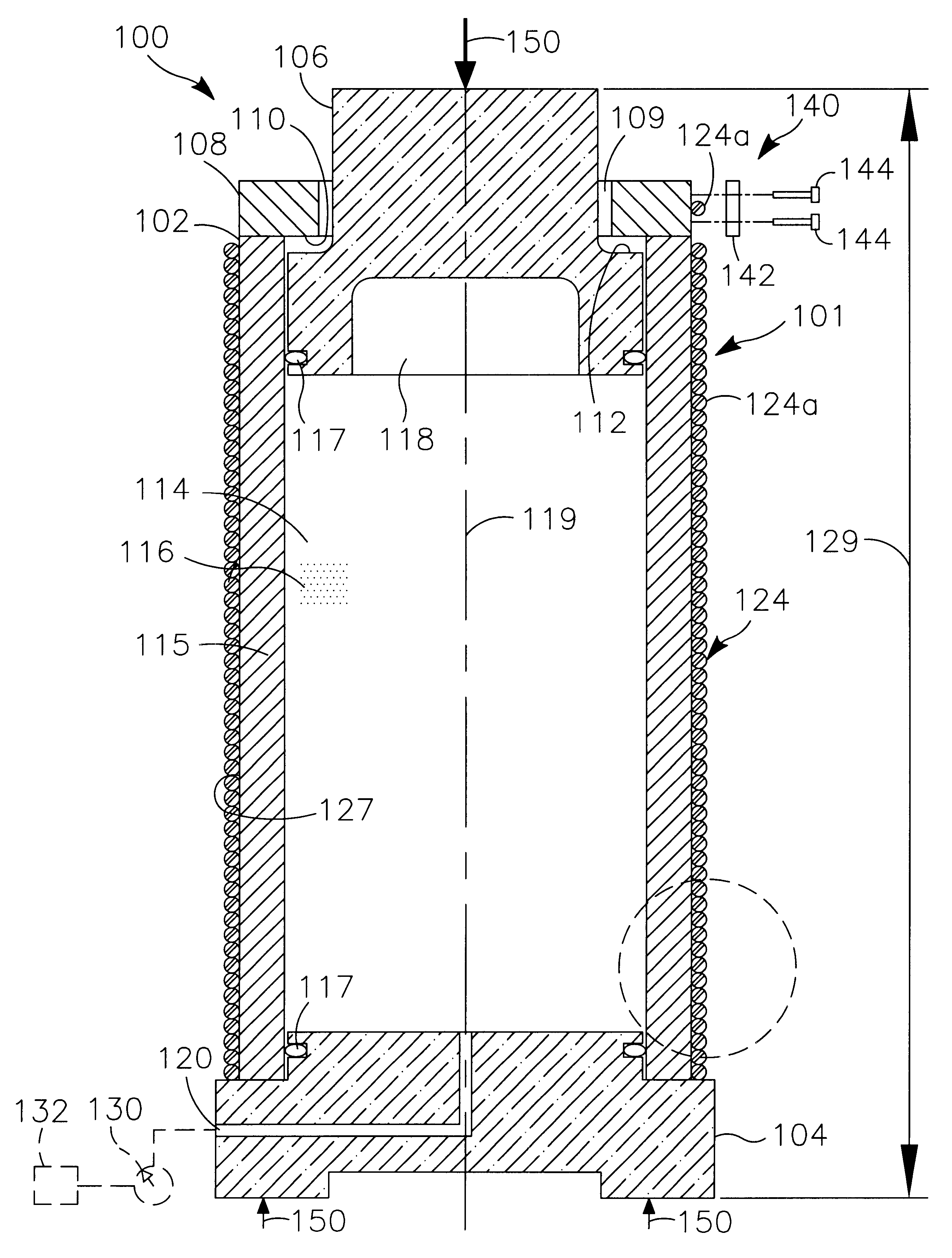
Fullscreen capture 5262022 104032 PM.bmpFullscreen capture 6212022 75358 PM.bmpFullscreen capture 6302022 113919 PM.bmpFullscreen capture 732022 120335 PM.bmp
Power curves for the Nibe A (below), Enercon E-44 and Enercon E-70. The power densities at 12 meters per second are 0.434, 0.46 kW/m2, and 0.48 kW/m2, respectively. It should be noted that the Enercon turbines, as well as many other turbine models, actually produce far more power than advertised since the power curve lies on the outer parameter of the power band distribution, in other words, the published power curve is the minimum power the turbine is guaranteed to produce under a given wind speed.
The Nibe A and E-44 are substantially more efficient than the mean wind turbine in use today, this is attributable to an optimally slender blade geometry. The Enercon E-70 currently boasts the absolute highest power density of any wind turbine existence thanks to its unparalleled CP of 0.45 at 12 meters per second, the E-44 has a CP of 0.44 at 12 m/s. The unique airfoil shape, which is readily observable with its highly cambered geometry, accounts for its high CP. The reason other manufacturers do not appropriate the airfoil design is unkown, since Enercon Gmbh does not maintain any patents in the Google patent archive or the European patent Espacenet search engine. 

Power curve of two E-44s installed in Iceland, showing up to 20% overproduction. 

Fullscreen capture 7292022 44807 PM.bmp

This chart suggests that there is no anomaly but rather that Enercon merely simply measures the minimum production and cuts off anything above the minimum, but since there is considerable variability in the local aerodynamic efficiency of the blade caused by changes in air density, particles, moisture, etc, this means there is quite a wide band of potential power outputs. If we take the midpoint of that green scatter plot they construct, the power density is nearly 600 watts/m2. This curve, although considerably more power dense than most models, is perfectly compatible with wind turbine physics and the Betz limit. The DTU wind map estimates the power density of a 12 m/s wind regime at 1.67 kW/m2, if the CP is 0.44 then the power density would be 0.73, so the CP is likely only 0.32.

Fullscreen capture 8112022 13501 PM.bmp

The Enercon E-44’s overproduction and the power law.

Ragnarsson et all performed a study on two Enercon E-44s installed near the Búrfell volcano in Iceland and found a dramatic overproduction compared to the power curve predicated by Enercon. They concluded that either Enercon underestimated the true power output to be conservative or that the particular site which featured an 8.7 m/s mean wind speed and a standard deviation of 5 m/s featured substantially more storm speeds in the 25-34 m/s range which could account for the higher power output. The authors concluded that it was likely that both factors accounted for the substantial overproduction, which of course is excellent for the wind turbine owner. Either way, the turbine produced about 17-20% more power at 12 m/s than the rated curve predicts, yielding a power density of 0.545 kW/m2, or on average producing over 850 kW at 12 meters per second. Since the Icelandic site is located in a class 3 Ice zone, one can assume at least a 5% power loss to icing, making its real power density perhaps as high as 0.57 kW/m2.

We can now turn to the power law of vertical wind shear profile. The entire modus operandi of our tower is to tap into faster wind speeds. The reason wind speed decays is because of surface roughness, which has a diminishing effect as height increases. Over oceans, wind speed does not decay as severely as over shrubs or forest, hence the higher speeds found over oceans. It is not that wind travels inherently faster over the oceans, it’s that more of its kinetic energy is preserved allowing it to maintain its momentum. For offshore installations, there is less incentive to increase height.

A number of formulas exist for calculating wind speeds at elevated heights, but the most common wind is the so-called power law, widely used by skyscraper designers to estimate wind loads. To utilize the power law, an accurate estimate of the surface roughness is needed. The power law uses an exponent which is a function of the roughness, which varies from 0.10 for oceans and over 0.2 for urban areas. One thing is to be noted, either the DTU wind map overestimates the vertical wind profile, or the power law underestimates it, because if one uses the power law with an exponent of 0.15 (typical for short prairie grass) the increase in wind speed from 50 meters to 200 meters is substantially less than the DTU estimate, which has likely been verified experimentally with SODAR data.

In the 1970s, the aforementioned Department of Energy “Project Independence” investigated designing a 300-meter tall tower to capture high-speed winds in Caspar Wyoming, they estimated a 1.093x wind speed increase from 182 meters to 300 meters, Caspar Wyoming is primarily short prairie grass. The Dutch offshore wind atlas measured a 1.075x increase from 200 to 300 meters over the Dutch countryside, which is mainly pasture with low tree density, but a higher density of buildings than the Argentinian prairie or the Nebraska sandhills. Assuming a wind speed exponent of 0.15, between 0.14 and 0.16 is realistic, then if we increase the height from 200 meters where we know the wind is 11.5 meters per second from the DTU map, we can then get a speed of 11.7 m/s at 300 meters. But this number is likely underestimating the true speed exponent, because if we compare it to the Global Wind Atlas, to match the speed increment from 50 to 200 on the Atlas, an exponent of 0.225 is needed, which suggests the mathematical formula is ill-equipped to calculate the true wind speed at elevated heights unless the DTU wind atlas is completely inaccurate, which seems unlikely. For example, in one selected coordinate, Magallanes, Santa Cruz Province, Argentina, the mean wind speed at 50 meters is 9.24 m/s but increases to 12.55 m/s at 200 meters, but the power law predicts only 11.38 m/s at 200 meters, a full 1.17 meters per second slower than wind atlas.
What is the true number?

The “true” number (which of course requires an anemometer to be placed at the altitude and coordinates in question for 100% confidence) is likely closer to the DOE estimate and the Wind Atlas, after all, they would be very careful to validate the exponent they used since they were making financial estimates based on the wind velocities. Without renting a SODAR or placing an anemometer on a tower at the site, it is impossible to say with 100% accuracy, the question is can we achieve a reasonably close approximation? the answer is a sound yes. A sight with a wind speed of 10.9 meters per second at 200 meters, which is much of the Nebraska Sandhills, at 350 meters, the speed should be very close to 12 meters per second.

Typical-power-law-exponents-for-varying-terrain

The issue of gearsets

The single biggest limitation in wind turbine technology after the heavy tower is the need for a speed-increasing gearbox. The rotational speed of the shaft from the hub is only about 25 r/min for a 750 kW 44-meter diameter turbine. The weight and cost of a 25 r/min dynamo would be exceedingly prohibitive. The way the direct drive systems work is by increasing the diameter to increase the velocity of the stator and rotor, so the actual velocity of the magnetic flux is close to a smaller diameter high-speed device. But these large diameter dynamos occupy a large amount of space and feature a large frontal area which places a heavy bending load on the tower from the drag it generates, the nacelle also adds significant weight. The mass of a 1500-1800 r/min synchronous generator is already nearly 3 tons, while if the speed is increased to 20,000 r/min, the mass declines to barely 150 kg, very close to a linear decrease. The average copper winding intensity of a 90 kW induction motor at 1500 r/min is approximately 0.47 kg/kW, no data is available for synchronous generators, but the numbers are expected to be close. This winding intensity translates into a direct cost of €4500/MW at present spot prices, or approximately 40% of the cost of the typical 1 MW synchronous generator, the rest being assembly labor, which makes perfect sense. In contrast, by adding only two additional epicyclic gears, we can increase the r/min from 1500 to 20,000 with only an extra few tens of kg of 40Ni2Cr1Mo28 (AISI 4340) steel, which is one-eighth the cost of copper. This is a very intelligent design trade-off, namely using slightly more of a cheaper material to reduce the amount of expensive material by a large amount. For a 20,000 r/min synchronous generator, the amount of copper needed is barely 100 kg, or €800. Mazères Propulsion is actively considering a generator-less configuration where small diameter low torque drive shafts are inserted on the exterior of the column to drive a generator on the ground. Such a configuration would eliminate one of the only major hazards faced by wind turbines: electrical fires: Perhaps surprisingly, fires are one of the leading causes of wind turbine failure, by removing electrical components, it is difficult to generate the necessary sparks to ignite flammable material. Mazères Propulsion is also investigating the use of non-flammable ionic liquids for gearbox lubrication. Many ionic liquids have viscosities as high as standard motor oil (50 centipoises) and possess superior tribological properties, also this is highly tentative and no present modeling is based upon the use of ionic liquids. Mazères Propulsion has designed a novel lightning-proof gearbox and generator module sealed within an anoxic atmosphere always under a slight positive pressure. This design makes it effectively impossible for the gearbox oil to catch fire. The generator module itself contains no flammable material, the generator is made of metal. The fire risk on the gearbox emanates exclusively from the gearbox oil which is submerged in an oxygen atmosphere. Denied oxygen, the gearbox oil cannot burn from a lightning strike. 

Fullscreen capture 6252022 60147 PM.bmp

A 1 megawatt 1500 r/min synchronous generator juxtaposed with a 20,000 r/min version. The amount of copper saved easily pays for the added gearbox stages. It should be noted that once the initial high torque reduction is performed, gearboxes last much longer at the higher speed section since torque is dramatically reduced even though friction and heat are somewhat higher. 

Some may object to the added gearbox challenges associated with operating at elevated speeds, namely increased friction, heat, and subsequent lubrication degradation. But such concerns are trivial compared to the cost savings that can be had from the smaller electrical machine. 

Without such speed intensifying gearbox, heavy low-speed generators that need permanent magnets, usually made from neodymium, must be employed, at a significant cost and weight penalty. These slow-speed permanent magnet alternators make additional use of praseodymium to increase the flux density at low speeds, and are usually ten or more times more expensive than high-speed synchronous generators or induction generators. Beyond a mere cost disadvantage, the weight of the generators even after adjusting for the weight of the gearbox makes it an unattractive option as it adds nacelle volume which contributes to greater drag that has to be borne by the tower structure, be it conventional or hydrostatic. Despite the high cost of permanent magnet dynamos, neodymium, and especially praseodymium, contrary to popular belief, most of these lanthanides are not “rare” at all. Neodymium reserves do not actually limit the scalability of wind power unlike platinum group metals limit the scalability of fuel cells.  

Technology is ultimately subordinate to the elemental and the material substrate it can be constructed from, and their techno-geological attributes. In the realm of structural engineering, man enjoys a privileged vantage point, since there exists only one non-ferrous alloy with a tensile strength of close to 1000 MPa, that is beryllium copper. Excluding titanium, virtually all of the high-strength metals available are ferrous. Beryllium copper is an ideal choice for extreme applications, its application include drill string collars, marine fiber-optic connectors, and spark-less tools. But since reserves of beryllium, primarily mined from pegmatite, total only 80,000 tons, and typical beryllium copper contains 2.5% Be, theoretical production is only 3.2 million tons of the alloy.

Man has not been kindly enough bequeathed with the more exotic of the elements, the most abundant elements he has access to are rather bland elements, that may shine in structural applications, but have limited electrically attractive properties, such as high conductivity or unique optical properties due to their electron orbital shapes. Iron is the most abundant metal after aluminum, and while solute strengthening, precipitation hardened, and plastic deformation can be performed to produce the strongest metal known to man, it has rather unextraordinary properties needed for certain highly specialized applications, such as catalysis or electronics. For any technology to be viable, its material constituent has to be scalable with the demand for said technology. A technology that cannot scale for reasons of elemental scarcity, is a useless technology no matter how impressive it may look. PEM fuel cells, and lithium-ion nickel-cobalt manganese batteries both cannot scale to worldwide levels of deployment, even though many technologies that use exceedingly scarce elements, for example, catalytic converters, have been scaled, but that is thankfully because they use such minute quantities. 

A low-speed permanent magnet generator uses an average of 650 kg of magnet per MW, and of that, 22% is neodymium and 0.76% praseodymium by mass, although some estimates suggest as much as 4 to 6% praseodymium is used. For medium-speed permanent magnet motors, the magnet loading is 160 kg, for high speed, it drops to 80 kg. Since the whole point of using a permanent magnet is to dispense with the gearbox entirely, we will choose the 650 kg/MW for our scalability analysis. The benchmark for all our scalability studies is the U.S or European power, which are both around 3-4 billion megawatt-hours a year. We would need 450,000 MW of installed capacity to power these big grids or close to 90,000 tons of neodymium and 3,000 tons of praseodymium. The estimated reserves of neodymium are massive, estimated to be 20 million tons, and praseodymium is estimated to be 2 million strong, so the scarcity of neodymium nor praseodymium is not a concern, but rather their added cost, weight, and volume occupied compared to a high-speed unit. An electrical machine’s power density is a linear function of its rotational velocity, so the worst possible thing we could do is operate the generator at low speed. A speed modulation system is far more elegant than squandering materials and manpower into constructing inordinately heavy low-speed machines.

Elemental composition of NdFeB magnets.

Material-compositions-of-virgin-and-recycled-NdFeB-magnets

Since our turbine operates for simplicity at 100% “capacity factor”, our annual power output is its hourly output times 8760 hours minus 3-5% maintenance downtime. 

While direct drive turbines suffer from numerous electrical machine limitations, gearboxes are not exactly perfect either. Wind turbine gearboxes have historically suffered from far from ideal failure frequency, caused mainly by cyclical torque loads caused by varying wind speeds. Unlike a gearbox used in industrial machinery operating at a constant speed, a wind turbine gearbox is subjected to isochronous loads, which cause a sudden introduction of torque placing dynamic loads in the gear teeth and prematurely wearing them out. The term “hydrostatic” when invoked with reference to wind turbine technology has almost always insinuated the use of some form of gearbox system for power transmission, namely to up the r/min to suitable generation speeds. Hydraulic fluid is incredibly convenient for designing an infinite-speed variator, but the losses have served to thwart this technology application. The use of ionic liquids, combined with short path flow circuits and low leakage seals, may open up the possibility of infinite speed hydrostatic speed-up variators, finally ridding the annoying gearbox from the wind turbine. While conventional hydraulic drivetrains as aforementioned suffer from an efficiency penalty relative to gearboxes, ionic liquids with their almost zero compressibility offer the drivetrain designer the ability to contrive a close to lossless pure hydrostatic speed variator. Ionic liquids boast a bulk modulus (a measure of incompressibility) of almost 3.6 gigapascals at 400 bar, while traditional hydraulic oils are around 2.2. This difference may appear insignificant, but for a hydraulic system, it makes a substantial difference in the net efficiency. The less energy is absorbed compressing the fluid, the more leftover for performing useful work. The second major cause of energetic losses in a hydraulic circuit is viscous drag and the concomitant pressure drop as the fluid is pumped at high flow rates in a long hosing circuit. Fluid loses momentum as it incurs viscous drag along the hosing wall and pump and motor surface area, since any given volume of hydraulic media contains only so much energy, the amount of viscous induced momentum loss is significant. An ideal hydrostatic power transmission circuit would minimize viscous losses to the greatest extent possible, this would be achievable by minimizing circuit distance, but there is limit to how small a circuit can be achieved.

It would make little sense to design a transformative and innovative tower technology without making at least some minor improvements to the main turbine module. A wind turbine, ours for that matter, that uses a high-speed generator, makes use of no scarce elements.

It would be remiss to say that the only defining feature of our turbine is its lightweight high altitude rigid pneumatic tower. We have concatenated a number of technologies to greatly boost the reliability, cost-effectiveness, and longevity of the system. We have already discussed at length the use of solid-spar machined blades which provide unparalleled fatigue performance guaranteeing long service life. Aside from the blades, the self-erecting system provides wind turbine owners with the ability to install the turbine without the use of cranes, as well as to disassemble the unit if needed in a short period of time. But perhaps one of the most compelling adoption advantages is the use of our novel traction drive speed increaser. It can be argued the gearbox is the “heart” of the wind turbine, without it, it is impossible to generate electricity since the speed of rotation of the blades is so low. The use of permanent magnet large-diameter motors is impractical and unattractive, resulting in a heavy mass penalty as well as a large increase in the turbine’s frontal area, increasing wind loads on the tower. But existing speed-increasing gearboxes suffer from premature failure due to the highly variable nature of a wind turbine, frequent torque spikes and transient loads cause gear tooth scuffing and fracturing, necessitating frequent overhaul thereby raising operating costs. In light of this problem, researchers have scoured alternative options, but so far, only hydrostatic transmissions have shown any promise. But hydrostatic transmissions result in high losses due to the compressibility of hydraulic and viscous pumping losses, making it an unattractive option. This leaves us with only one option, since cycloidal drives are not attractive due to vibration, we are left with traction or friction drives, widely studied in the 1960s by automotive manufacturers but for a number of reasons, failed to gain any momentum. 

Richard A. Himmelmann at Raytheon Technologies Corp patented a traction drive for wind turbines in 2012 under the U.S patent 20130343889A1 titled “Friction Wheel Drive Train for a Wind Turbine”. The design is quite a bit different from ours as it makes use of individual dynamos mounted to each traction drive roller element. This design we belief is far from ideal, even though the initial stroke of genius to use a traction drive was made by Himmelmann and full credit goes to him even though we independently invented it. The Mazères Propulsion design uses two Cardan joints to transfer the high torque low speed power 90-degrees to a large diameter traction drive wheel where 8-high speed roller elements are pressed together with hydraulic traction cylinders. The generator then mounts between these higher-speed roller elements to further increase the RPM to 8000. The traction drive is lubricated with specially formulated traction drive fluid which can produce traction coefficients of 0.11 or more. The entire drivetrain assembly is encased within an argon atmosphere to minimize fire risks.

Fullscreen capture 5102023 122734 AM.bmpFullscreen capture 5102023 122719 AM.bmp

US20130343889A1-20131226-D00002

Friction Wheel Drive Train for a Wind Turbine, US20130343889A1, Richard A. Himmelmann, Beloit, WI, Raytheon Technologies Corp

Magnetic and Hydrostatic bearings

Wind turbines are subject to very large axial and radial loads. The 44-meter turbine has blades that weigh has 1,600 kg/ea and a hub weighing 600 kg. The radial loads not only emanate from the dead weight of the rotating equipment, but also from the wind force acting on the blades laterally. An additional ten more tons may be generated by strong gusts acting on the side of the blades. Therefore, a wind turbine bearing must have very strong lateral load capacity as well as gravitate vertical load capacity. Since the parasitic power loss is proportional to the bearing friction, and friction is proportional to the force applied, a heavy shaft spinning even at low speeds incurs a small power loss, which of course would need to be larger than the power required by the hydrostatic or magnetic bearings. This is where the crux of the matter is, as all alternative bearing technologies actually have greater parasitic losses than ball bearings, their improved lifespan and reduced maintenance cost must offset their greater parasitic power. In some cases, this may not be fully compensated by their superior longevity. An axial ball bearing with a typical friction coefficient of 0.005 will incur a power loss of 320 watts, or 500 N for an 800mm diameter shaft spinning at 20 r/min, or approximately 0.00053% of the output power. This is truly a testament to the efficacy of contact-bearing technology!

Magnetic bearings rely on the repulsive and attractive force of an electromagnet to produce the levitating force necessary. The achievable zero-gap forces are between 50,000 and over 70,000 kg/m2 for electromagnets, but at a gap distance of 1 millimeter, this would decrease by about 17%. At 2.5 mm of gap, the force declines 30%. Magnetic field intensity declines as the inverse cube of the distance, so it is desirable to maintain as small a gap as possible, but there exists a clear limit on how close they can come, since the bearing has some degree of movement within the magnetic confinement. 

The power requires by an electromagnet varies from 3 mW/kg to 10 mW/kg, depending on the flux intensity, more current running through less winding generates more heat and eddy current losses. The average power consumption is around 10 mW/kg for a magnetic pressure of 60,000 kg/m2. For a conservative estimate, we will use 12 mW/kg, thus for a 10 radial load-bearing, we will consume 1 kW, or three times more than a friction roller bearing. At first glance, this would seem like the ideal magnet design, but upon further examination, there are some notable issues that have served to keep this technology from reaching mainstream use. A central issue has been the relative bulkiness and cost of the copper winding, the second has been the need for precise balancing of the shaft inside the electromagnet coil array. Precise gap sensors operating at high frequencies feeding into a digital controller are necessary for stable operation, this has served to dissuade designers from incorporating magnetic bearing in all but the highest speed and critical applications. The other issue is lack of redundancy, all magnetic bearing systems require an auxiliary friction bearing that must be capable of relieving its load before the magnetic bearing is turned on during startup. Moreover, if the magnetic bearing fails, catastrophic failure would occur without the ability to carry the shaft’s load on an auxiliary bearing. The amount of volume needed is substantial since the relative magnetic pressure is very low compared to hydrostatic bearings or conventional friction bearings. 

In contrast, an externally pressurized hydrostatic bearing would generate a pressure of 700,000 kg/m2, allowing for a much more compact bearing package. Using pressure drop as our flow rate determinant, we can calculate the pumping power of the bearing. For an oil film thickness of 50 microns, which is typical for a hydrostatic bearing, if the diameter is 800mm with a length 350mm, assuming a steel surface, a flow rate of 20 liters per minute generates a pressure drop of 100 bar. The pumping power is thus 6000 watts, or sixteen times more than a friction bearing. If reducing friction ends up increasing the power lost in the system, one has to ask whether this is a sound engineering decision.

In conclusion, there is little reason to believe bearing technology is receptive to significant improvement effort, leaving other systems as prospective candidates for process intensification and betterment.

What is needed rather than sundry marginal micro-innovations, whether in speeding modulation, bearing technology, or even blade aerodynamics, is precisely the antonym of a micro-innovation: a macro-innovation. A departure from the world of incrementalism and minor tweaking is needed, a radical leap onto a higher plane of technology is called for. A Kuhnian paradigm shift and revolution in the way structures are constructed, away from Euler columns towards hydrostatic columns, is wind energy’s new calling. This paradigm change in the way we support wind turbines, an “aerial platform”, that allows the designer to place the state-of-the-art windmill in the fiercest wind regimes in existence, all while staying within the safety and comfort of the solid ground, culminates in a unique technological optimum. This technology allows this designer to capture wind speeds equal to the best offshore wind farms without the corrosion and foundation penalties encountered by the oceans.

Structural dynamics and the unique properties of the pure-tension tower

The following text is meant to be a brief exposition on this new type of technology, one that can greatly potentiate the power of wind energy.

A cable-stayed bridge in China. Cable-stayed bridges are among the few terrestrial structures that make extensive use of cabling to derive their structural integrity and distribute loads.

Sutong_Yangtze_River_Bridge (1)

Mazères Propulsion invented this technology in February 2022, after many months of studying how to improve wind energy by increasing turbine operating altitude. A fascinatingly novel structure, that defies the norms of structural engineering, arose out of this effort. The technology is so novel that an entirely new vocabulary must be developed, entirely new concepts have to be normalized and contemporary literature must be updated accordingly. This new type of pure tension tower is ready to be exploited with zero research and development required, using only contemporary materials procurable from commercial supplies, and using the current knowledge of gas sealing, compression, ferrous metal fabrication, and cold-drawn metal wire rope manufacturing. The technology’s compatibility with extant material and know-how means that it boasts a technological readiness level at stage 8 or even 9. Initially, it is expected that only minor logistical and erection challenges will be faced. Although a number of effective and reliable systems must be developed to make the self-erecting system (discussed at the bottom of the article) to reach a level of predictability and reliability needed for widespread commercial use.

In consequence of the vast power of hydrostatic force merged with structural engineering, a tower can be designed to reach heights of 1150 feet or 350 meters permitting wind developers to tap into inexhaustible amounts of high-velocity wind energy previously squandered out of a lack of suitable options. The use of the term “self-tensioning” highlights the structure’s ability to generate autogenous rigidity from the upward force of the desirous to expand hydrostatic media (liquid or gas), as well as to stabilize itself through the tensioning of guy cables. A third feature is the structure’s ability to elevate itself using a sequential tube-extension mechanism, what we have termed “autogenous erection”, which obviates the need for costly and bulky cranes for erection and their attendant transportation. This feature alone saves several tens of thousands of dollars on each turbine erection, further minimizing the LCOE. 

The basic concept of using pressure to generate rigidity is itself not new, inflatable domes make use of it, but offer only rudimentary spherical structures with limited use. Despite no commercial application and the high degree of novelty surrounding this hydrostatic structural technology, it would be fair to say virtually every conceivable humanly possible idea has been patented in some variation or another, even if not exactly homologous, it’s hard to not to find a remote conceptual cousin in the patent literature, who for unknown reasons, floundered commercially. It would be hard to believe no one had imagined using the force of hydrostatic or pneumatic fluid to carry heavy loads in structural applications, low and behold a tiny number of people have, but the literature remains completely obscure nonetheless and this patent literature has not spilled over into textbook literature. The first person to seriously investigate and publish a technical article on the possibilities of pneumatically supported structures was Jens G Pohl at the California Polytechnic Institute in San Louis Obispo. It should be noted that the concept of a “pneumatic structure” is nothing new, but when the term is used, most people think of air domes, hardly a stiff and strong structure. Our inquiry into pneumatic or fluid-filled structures is strictly with the aim of achieving unparalleled stiffness, equal to or greater than conventional metallic structures which rely on the material’s elasticity modulus for stiffness. In 1967, Jens Pohl published a paper titled “A Preliminary Investigation into the Load-Bearing Capacity of Open-Ended Cylindrical Columns Subjected to Internal Pressure” at the Proceedings for the International Colloquium on Pneumatic Structures in Stuttgart, West Germany. Jens Pohl maintains an active website and authored a book on pneumatic structures, but makes little to no mention of the rigid pressurized column, but instead focuses on his concept for a pneumatic high-rise building using flexible membranes for pressure containment. Pohl constructed a small inflatable polyethylene bag using pressure to carry load, but due to the fact that the plastic piston readily transferred friction to the edges of the flexible plastic tube, it did not perform as a true pure tension tower. The “Pneumatic structures Colloquium” in Stuttgart is no longer held, pneumatic structures have found no widespread use due to their inability to be configured into a geometry that achieves high stiffness. Pohl’s 1967 paper on pressurized columns is not available to read, but judging from the title, it appears as if his intention was almost entirely homologous with ours, but it seems he has moved on to more flexible designs in recent times. Despite Pohl being the first, he is not the one that can be credited with the idea for designing a truly rigid and hydrostatic structure, that title belongs to Milton Meckler. Meckler is still active as a consultant, but has made little inroad in developing his ideas in hydrostatic building technology, not due to the merit of the technology, but entirely imputable to incorrigible industry dogmatism. In November 1970 Milton Meckler patented a design for using hydraulic fluid inside tubular members for mid-rise building construction, he went on to patent two other variations of the initial design, none have seen any commercial use. The concept was to use circumferential tension or “hoop stress” to absorb the otherwise compression and bending loads in ordinarily loaded structural members. Using compression to carry tensile loads is by no means a novel or unproven concept, worldwide, cable-stayed bridges experience superlative performance by transferring their loads to compression in concrete or steel columns. These bridges perform superbly in high winds, cable drag or vortex shedding surprisingly proves to be of little liability.

Meckler, as in our designs, does employ a free-floating piston at the ends of the hollow tubes, each of these pistons is then connected to an intermediate member which connects the tubular-truss configured members as highlighted in the image below. In 1981, Meckler published a book titled “Energy Conservation in Buildings and Industrial Plants” where his concept for fluid-filled tubular members was cited, but not discussed in detail, but the idea was never cited in successive literature.

Meckler’s hydraulic building system.

US3538653-drawings-page-1

After Meckler, the closest anyone has come to developing a true hydrostatic structure is computer graphics developer Melvin Prueitt, who conceived of an inflatable flexible fiber composite multi-story structure over a decade ago. In 2009, Melvin L. Prueitt patented an inflatable structure drawing its rigidity from compressed air using low compressive strength fibers. Prueitt called his invention a “Compressed-Air Rigid Building Block”. Prueitt’s design employs pneumatics, and uses Vectran fiber “pockets” stacked to form a rigid tower. Prueitt, like Meckler, has found no takers, again evidence of a chronic poverty of imagination in the building and structure community.

Prueitt’s pneumatic tower using Vectran “blocks”.

US20090260301A1-20091022-D00006US20090260301A1-20091022-D00000

Prueitt comes arrived at the concept of using lateral guys, using pressure as a source of rigidity, and loading is material in tension only, but unlike the following patent, failed to make the connection with free-floating reciprocation of a piston.

As can be seen from this quite diverse prior art, Mazères Propulsion is not alone in our inquiry into a new class of structure, but we are alone in seeing their newfound potential, and we are responsible for the final design refinement which we will mention later. In 1984, Jack G Bitterly patented a hoop-stress-loaded hydraulic column to bear vertical loads. Bitterly’s design comes very close to ours, and is effectively our design except the only difference is that in ours the guy cables are oriented laterally. But even Bitterly’s design is not certain to be a full pure tension structure, since the piston ring sealing mechanism can still transfer compression to the walls.

Bitterly’s hydraulic “Euler buckling free” slender column patent drawings.

US4685253-drawings-page-2

US4685253-drawings-page-4

The following is from Bitterly’s patent description: “The pressure tube is mounted such that it can move axially with respect to the cable or the outer tube. When the tube is pressurized, some of the force is absorbed in hoop stress in the tube, and some of the force is directed to the ends of the pressure tube and to the cable or the outer member either through a piston arrangement or otherwise. When compressive loads are placed on the system, it can support force up to the preload without exhibiting Euler buckling. The system is useful for long, thin columns and for long beams where rigidity is important. The pressure tube is not subject to compressive loading because its ends are free to move axially without compressing the tube. The pressure tube may be wrapped in high tensile strength unidirectional fiber material to withstand higher hoop stress”.

By no chronological order, below is a list of homologous hydraulic or pneumatic structures that individuals have patented throughout the years. It is interesting to note that this is what we see in the patent archive, it is reasonable to expect there are private documents within corporations or government bodies that have not been published that allude to similar concepts.

In 1951, Archibald Milne Hamilton patented a design for a pneumatically supported tower structure, which according to the patent description, would use air at 80-100 PSI to generate rigidity, but he does not employ the use of a free-floating piston, so he cannot perform the feat of self-tensioning. Below is the patent drawing for Hamilton’s pneumatically rigidified structure.

In 2001, William E Drake patented a pneumatic column structure titled “Column structures and methods for supporting compressive loads”. In the patent, he describes the use of a hoop-stress-loaded composite fiber column filled with gaseous mediums to be used in supporting compressive loads. But unlike Bitterly, he does not use a free-floating piston.

In 2008, Michael Regan patented a pneumatic column entitled: “Fluid pressurized structural components”. The design is a constant volume containment unit.

In 1993, Raul A. I. Schoo patented a design for a hydraulic load-bearing column titled: “Tubular column of high resistance to buckling” with intended use with hydraulic or pneumatic media.

In 2010, Elberto Berdut Teruel patented another design for a hydrostatic column member titled: “Compressed fluid building structures”, the design seems to be very similar to Drake’s patent. Despite Teruel’s patent being accepted by the U.S patent office, Teruel promotes quacky free-energy gimmicks on his website, which is often the downside of creativity.

In 2010, Charles R. Welch et al patented a hydrostatic structure they named “Hydrostatically Enabled Structure Element (HESE)”, this design also appears virtually identical.

In 2004, Roland B. Heath patented yet another hydraulic column titled: “Load-bearing pressurized liquid column”. This patent again appears virtually indistinguishable from the above designs. Below are sundry images from the above patents. As can be evidently seen, they seem to follow a pattern: they are rudimentary cylinders that use hydraulic fluid to carry loading in a column-like regime, but none went to the next logical step which is to generate autogenous tension in the guy cables.

Below are sundry images of the above-mentioned patents in no particular order. The following patents can be studied in further detail in the source section at the bottom of this page.

US08245449-20120821-D00003Fullscreen capture 6172022 111707 PM.bmpUS08245449-20120821-D00000US06484469-20021126-D00000US2738039-drawings-page-1US5555678-drawings-page-2US20110047886A1-20110303-D00000US07232103-20070619-D00002

JP5033273B1-16JP5033273B1-15JP5033273B1-14

Pressure Membrane Composite Structure, JP5033273B1, Tatsuya Endo

A freestanding space elevator tower for launching payloads, tourism, observation, scientific research and communications. The space elevator tower has a segmented elevator core structure, each segment being formed of at least one pneumatically pressurized cell. The pressure cells may be filled with air or another gas. Elevator cars may ascend or descend on the outer surface of the elevator core structure or in a shaft on the interior of the elevator core structure. A payload may be launched from a pod or deck at the upper end of the space elevator tower. The space elevator tower is stabilized by gyroscopic and active control machinery. The space elevator tower maintains a desired pressure level through gas compressor machinery. Methods of constructing the space elevator are also disclosed.

Space elevator, US9085897B2, Brendan Mark Quine, THOTH TECHNOLOGY Inc

US09085897-20150721-D00002

Prueitt and sundry patents do not make full use of freely floating reciprocating pistons, nor do they make use of guy cables fastened in a lateral orientation, but what they do have in common, and hence their citation in this exposition, is that they all use the pressure of some form of hydrostatic media to generate stiffness. A pressurized fluid-filled system can either be in the form of fixed or variable volume containment structure to generate their rigidity and bypass Euler buckling via hoop-loading, of which they otherwise possess very little, if not none as in the case of Prueitt’s compressed air rigid building block which uses Velcran fibers. An important distinction to make and in fact the main distinguishing feature that allows us to separate and categorize these respective hydraulic and pneumatic structures is the difference between a fixed and variable volume system. The two main architectures of a hydrostatic structure regardless of its material composition, geometric orientation, or hydrostatic media. A fixed volume hydrostatic structure will of course pressurize its surrounding walls, and it will generate tension in its longitudinal direction, but because it is of a relatively fixed volume, it cannot perform the act of external self-tensioning. What all of these patents excluding Bitterly’s have in common is their use of a fixed volume column. A variable volume hydrostatic structure is where the free-floating piston is free to move longitudinally to the extent that the restraining guy cables permit it to. This affords the potential to generate longitudinal tension externally and subsequently permits the bearing of lateral loading such as wind shear loads, this is an exigency for wind turbine towers, whose static wind load can often exceed the weight of the actual turbine itself. It is only Bitterly’s design, which is most homologous to ours, that performs the stroke of genius to employ the free-floating piston which generates a variable volume chamber. Bitterly cleverly uses a high tensile cable fastened inside the tube submerged within the fluid to retain the pistons at both ends of the tube. Despite this extensive but overlooked patent literature, hydrostatic structures remain an anomaly and arouse strange looks among even educated structural engineers. The relatively extensive patent literature serves as corroboration to those who are skeptical of the technology’s feasibility, since after all, each patent is examined by a qualified examiner, so almost everything in the patent literature must be somewhat technically feasible to be approved as a useful invention. Interestingly enough though, according to U.S patent law, a technology does not necessarily have to be compatible with the present “laws of physics” to be approved, hence there can be found patents pertaining to electrogravitics or other yet-to-be-demonstrated phenomena. Of course, patents alone cannot be used to evaluate any technology, since there are invariably a significant number of patents that make it through despite having dubious technological feasibility. A technology can be only evaluated by a methodological and holistic analysis of its working principles and methods to attain such working principles. In light of this rich “prior art”, it is surprising there has been no effort to harness the immense force and rigidity generation of hydrostatics for structural applications. Despite the huge upside, there is not a single terrestrial structure that uses this brilliantly novel concept of bearing a load using the internal pressure of a cylindrical pressure vessel as opposed to transferring it into the wall of the structure via compression.

There’s an inherent paradox in the science of invention. This paradox arises because the inventor actually wants both novelty and a degree of familiarity to make said invention readily understood and compatible with known physical principles and science. Since constructing a prototype often requires considerable sums of capital to be raised from investors, ultimately, the inventor must be quite confident the invention is viable prior to its demonstration. This is why the argument “build a prototype” or else we cannot evaluate your idea is flawed, most inventions in history started off as drawings and went on to inspire so much excitement and confidence that businessmen poured money on them in the hope of a huge payoff. Because society and nations are always operating within a competitive dynamic, everyone is trying to out do each other, so no invention goes unnoticed for long because of the commercial upside potential. This competitive dynamic is especially pronounced in military affairs, since a smaller army or nation can win against a more powerful opponent by perusing a better technological accouterment. For example, the origin of canned food dates back to Napoleonic times when armies became so big as to outstrip the available local food supply they could gather from nearby farms. The food problem was so acute that Napoleon tasked a commission to study the possibility of preserving food. One of the first attempts was to place food in a glass bottle and heat it to sterilize it, glass was used by the French for lack of tin, while the British used tin thanks to their productive tin mines dating back centuries.

There is thus this antinomy that the inventor subconsciously desires both novelty, as to make his invention truly an invention, but also guaranteeing a minimum degree of certitude and familiarity. Yet another paradox is that the more “inventive” the innovation is, the more it befuddles the best minds, making it more difficult for a critical analysis to be performed. For example, Rudolf Diesel sent his manuscript “Theory and construction of a rational heat motor with the purpose of replacing the steam engine and the internal combustion engines known today” to Lord Kelvin who readily praised it because it made perfect sense to his thermodynamic mind. In contrast, many modern innovations are so difficult to comprehend, say in DNA sequencing or nanotechnology, as to make them extremely difficult for a moderately technically skilled person to evaluate. This may explain the prevalence of very dubious startups pitching gimmicks who are spun as “groundbreaking” as to even befuddle the experts. There is yet another pernicious myth and that is the notion that technologies have been suppressed throughout history and that inventors were persecuted. This argument has been used to justify scams including Theranos. Elizabeth Holmes repeatedly made this statement in her defense. Cases of ridiculed inventors include Richard Trevithick who was called a “madman” by James Watt, his steam train earned the title of “puffing devil” by local onlookers. Early airplanes were believed to be unable to carry guns onboard as the recoil energy would cause them to “capsize” in air. There was also a believe that early airplanes could never scale above a certain size as the wings would become heavier than the available lift. Yet another belief was that if two engines were installed on the airplane that it would become too unstable to pilot. In 1911, a prominent engineer wrote in an electrical journal that the gas turbine would be “impossible” and the British society of mechanical engineers discouraged people from pursuing the idea. It is perfectly fair to argue that most people failed to anticipate the groundbreaking innovations that occurred throughout history, but no one suppressed them. It is perfectly true that simple people scoffed at brilliant ideas, but there is simply no evidence that anyone had sufficient power to suppress them. It is likely that rather than suppression and or persecution of inventors, the general public and society in general are often simply too ignorant and shortsighted to appreciate them and henceforth we have this modern legend of the persecuted lone inventor. It is also the case that invention is rarely a spontaneous lone event without a considerable trail of prior art serving as inspiration. The inventors of the steam engine were not without intellectual precedent, Papin, Giovanni Branca, and John Wilkins, not to mention Hero of Alexandria’s Aeolipile a millennia before. The principle of using expanding gas to drive something was known to men of learning prior to Savery. It would be a mischaracterization of history to claim that most inventions were without precedent or hardly understood by learned men of the time. Take for example the principle of magnetism, it was understood centuries before any technologies made use of it. Lodestone was a curiosity across the ages and it was known to the Greeks that metal objects could be attracted to these strange rocks. One did not necessarily have to understand the geometric pattern or field intensity of the magnet to utilize it for a compass.

Those who are skeptical should look towards existing technologies that are at least remotely homologous to ours. One such example are cable-stayed bridges, while not employing pressure for load bearing capacity, they do nonetheless rely on cables for stiffness. Structurally, there is no difference between a guyed tower and a cable-stayed bridge, the only difference is that a guy tower is elastic, it is vertically compressible, and hence laterally flexible, while a cable-stayed bridge is much less elastic since the dead weight of the deck serves to constantly tension the cables. Unlike the classic guy tower’s flimsy hollow tubular lattice tower, the cable-stayed bridge employs heavy duty reinforced concrete columns that are extremely stiff vertically, although not necessarily laterally rigid. Despite the weight of the deck maintaining a relative degree of rigidity, the deck is still not entirely stiff, in fact, it is free to flap in the wind if the load is sufficiently high, although since the Tacoma bridge, most designers have maintained a minimum degree of deck deadweight to prevent aeroelastic flutter. A common perception is that Tacoma bridge collapsed due to a resonance effect where the wind oscillations matched the deck’s natural frequency, this is a major misconception, the wind load was constant and not cyclical and did not come even close to the natural frequencies of the bridge deck. The failure of the Tacoma bridge was simply caused by the low weight of the deck which was effectively turned into an airfoil by the wind, so called aeroelastic flutter. Early aircraft wings experienced this fluttering phenomenon when designers did understand that they needed to insure the wing had to be extremely stiff and not excessively supple. 

The key to understand a stayed structure, regardless of whether it is a pressure derived or conventional one, is that tensioned cables that are prevented from elongated can only pivot around a fixed axis. This allows one to generate a very stiff structure if this pivoting action is canceled fully. Intuitively, it is obvious that the only way to perform this is by preventing vertical descent, since pivoting in the downward direction results in a reduction in height. A cable of fixed length cannot pivot laterally unless it follows its height-dependent angle. As a cable pivots, it follows a circular path that revolves around its fixed pivot point at the start of the cable, to move just a few degrees, it must move downward a significant distance, unless this can be facilitated by a height reduction in the column, a structure can be laterally as rigid as the force acting upward. This lack of any force pushing the tower up allows it to bend in the wind, whereas a pure tension structure is constantly being “pulled” or pushed up, whichever analogy one prefers, ultimately this is the same action. It is as if a gigantic crane were suspending and pulling the whole thing from the air, keeping the cables taught and preventing any sagging of the column. This is the key concept to understand and why one can never compare a pure tension tower with a classic guyed tower. A classic guy tower has nothing but the stiffness of its flimsy lattice structure to keep it aloft, a pure tension tower has hundreds of tons of force trying to snap its restraint cables, it is a completely different beast. Furthermore, the entire pressure column, the hollow tube which retains the fluid, does not bear its own weight, the column is actually always levitating, its deadweight carried by the force of the piston since the bottom of the tower is free to reciprocate as well on a separate foundation-mounted piston, which rather than pushing up, pushes down on the pad foundation and ultimately is born by the bedrock or soil. The only compression bearing component is of course the foundation, fundamental physics and mechanics forbid us from entirely eliminating compression, such a proposition would entail levitation.

CodeMeterCC 2222022 101442 PM.bmp

This image readily illustrates this pushing force. Since the column is kept perfectly level by the four lateral restraint cables being the exact same length, the piston cannot swivel in its cylinder or bend the column. The piston remains vertically level and pushes tightly on the four vertical and lateral restrain cables. This means that even if the wind does want to bend the tube side to side, the tube is still being stiffened by the force of the vertical restrain cables pulling on the tube stabilization cables pictured at the midpoint of the tower. One analogy is a vertically upright cannon, firing a projectile into the air, imagine the projectile was somehow restrained and could produce thrust indefinitely, such a strange configuration would result in the same principle: permanent stiffness from tension and pressure.

The nature of structural loads

Structural loads can be broken down into two basic categories, uniform, that is isostatic loads, and directional, heterogeneous or “multiform” loads. The force acting on a slender (assumed to be solid) column is both compressive and torsional, that is deformative, in that it subjects a plastic material to deformation. The reason for this is very intuitive. Metals are comprised of a crystalline lattice structure of atoms, these atoms can slide with respect to each other. Imagine taking a long row of marbles, stacking them up perfectly, and applying a force between both ends, one of the marbles within this row will invariably be ejected from the row and pushed out orthogonally. The only difference between the marble analogy and the metallic crystalline lattice is that the atoms are “sticky”, they are prevented from sliding excessively which is what makes metals stiff, they cannot merely fly out like our marble, but they can deflect ever so slightly. This deflection is what gives every metal its elastic modulus. If we multiply each atom by the distance and number, we arrive at a huge potential deflection moment by applying even a small compressive load to a narrow member. For a slender column, this failure mode is the well-known “Euler buckling”. This buckling dynamic will occur above a certain slenderness ratio, usually around 30. Euler buckling occurs far before yield is reached, the buckling is entirely facilitated by the material’s modulus of elasticity, all plastic materials are somewhat elastic and can elastically deform somewhat before permanently yielding. In contrast, flexural buckling or crumpling, such as in the case of a soda can, occurs when the thin wall materials elastically deforms and then yields. The last form of of buckling is pure compression failure where the material reaches its maximum compressive strength. Most steel columns will fail via either Euler buckling if they are very thin, or flexural buckling if they are wide but possess thin easily crumpled walls. The Pure Tension Tower (PTT) is loaded exclusively in tension (for the main cables) and hoop stress for the pressure column. Hoop stress can be easily calculated with the formula below, which has been empirically derived and remains very accurate assuming the seam strength is close to the material strength. While it’s easy to calculate manually, we have corroborated our calculations with the calculator below. It should be noted that the stress produced by this equation is around 5% less than predicted by Altair Simsolid. The formula for hoop stress is: σh = p * d / (2 * t). Where p is pressure, d is diameter, and t is thickness, σh is stress in MPa. Our optimal media column is 750mm in diameter for minimum drag load, with a pressure of 3.4 MPa, generating 150 metric tons of force. The weight of the tube-section is 68 kg/m with a wall thickness of 12mm. The total hoop stress on the cylinder is only 127 MPa, with 63 MPa of longitudinal stress. The elastic expansion of the cylinder is 0.72mm in diameter and a 0.2% increase in volume.

There is no free lunch in structural engineering, you may escape classic Euler buckling by increasing the diameter of the column, but then you will simply move the failure mode to another kind, namely flexural buckling and crumpling. Slender or thin-walled columns have very limited compressive load capacities, and hence high altitude towers are effectively impossible without the use of inordinately heavy thick-walled steel towers.

applsci-08-01602-g005Buckling-of-columns

But before elucidating the working principle, it would be useful to highlight the difference between a pressurized or “energetic substance” and a placid but highly firm material. Ultimately, the force from a compressed gas or liquid derives from intermolecular repulsion, which is electrostatic in nature. Gases possess very high average molecular velocity, this combined with their neutral charge prevents them from agglutinating into heavier compounds. The force that causes air molecules to repel each other is ultimately the same force that causes metal atoms to solidify tightly together, resisting intra-crystal sliding and generating a hard substance we can use for structural purposes. The difference is the energy levels of the metal is at equilibrium, there has been so external application of force, while for our liquid or gaseous medium, the energy levels are excited, in an unnatural state. In the case of a metal or solid, say stone, the atoms may solidify strongly, but they do not contain any releasable energy that desires to take the path of least resistance, they are stable systems in harmony with their surroundings. A gas in a compressed state is highly unnatural, just like a highly reduced metal, that wants to go back to its oxide state. Therefore, a dam carrying meters of water or a pressure vessel in a CNG car, are both systems that desire to release energy in a sudden burst, while metal experiences no such urge, yet both states have the potential to generate the same result: a rigid state. The reason a comparison is of value is that both aggregate states have the potential to generate rigidity or a firm surface, so we can now do something intuitively strange, compare an elastic, buoyant, compressible, and otherwise formless gas to a hard, solid material like metal. The difference is simply that to generate a firm condition with a compressed otherwise very elastic and buoyant substance we must put energy into them, but never allow the energy to be released, the energy is effectively levitating or hovering but never being allowed to flow to its natural diffused state. In this case, we are but a “receptacle’ for the energy of the contained pressure media, always exploiting its force, but never depleting it. It should be also noted that no structure, no matter how rigid the material may appear, be it steel or concrete, does not generate an equal opposite forcing countering the force acting upon it. A hydrostatic structured always produces a force greater than its rated load, meaning that deflection is actually impossible, just as it would be impossible for a man to pull a semi trucking driving down the road with a rope as it’s accelerating. Every load that does not exceed the hydrostatic force is countered by the structure’s momentum, a steel or concrete structure has no impulse or dynamic tendency, in fact a steel beam can be deflected ever so slightly even if the load is insignificant since the material by nature is elastic and there’s nothing acting to counter the force other than the material’s modulus of elasticity. While steel has an immense modulus of elasticity, around 200 gigapascal, 200,000 MPa, a force close to the yield strength for a relatively slender member can cause a substantial amount of pre-yield deformation. Since the pressure in the vessel is constant, it is not possible for the piston to be pushed down by the load and compress the gas inside, even micron-sized deflection is impossible. In other words, since the structure is always overloaded, that is the hydrostatic force is greater than the sum of all forces acting on it, it can never deflect downward, even minute quantities, unless there was a depressurization and subsequent structural failure. For deflection to occur a force greater than the hydrostatic force is necessary which would not occur during the structure’s lifetime. If this overloading were to occur, the pressure column would slightly expand laterally according to the newly increased pressure and accommodate the added pressure, but the piston would still not deflect downward any considerable degree since the added pressure would be merely absorbed by the tube, but it would not cancel the previous pressure or reduce it unless the tube reached its yield strength. Ultimately, this gambit of generating “free rigidity” from pressurized gas still of course requires a stiff material, otherwise it would merely act like a balloon when inflated, growing as its being inflated. A rigid material, be it metal or a fiber composite loaded in tension, there is no free lunch, we need material to bear the pressure, the crux of the matter is the nature of the loading regime. It just so happens that geometry makes an immense difference in how the same material reacts to a load, especially an isostatic load, and so one can interpret this technology as a geometric loophole that we are free to exploit: plastic materials perform much better in tension when they are free from non-uniform deformation, merely stretching in unison. Even if we still have to bear the force of the energized gas, hoop-loading is still far more structurally efficient, it is how we load the material that matters, not how much we load the material, since by definition there can no be no “free strength”, loading the column by pressurizing produces the same amount of stress as placing a vertical load on it in theory, but the behavior of the member under this equal loading regimes is hugely different. The same material, be it metal or fiber, may perform spectacularly when in a hoop-mode, but fail miserably when placed under a compressive load. The same aggregate amount of force is ultimately present in the system, in the same force density or stress, but the direction of this force is pushing out on the member (pressure column) which prevents it from elastically deforming, while in a vertical compressive regime (compressive loading of the tower), the force readily exploits the material’s elastic tendency. One can use a crude analogy of swimming up a river, the water bears our weight, but works against us, while if we swim downstream the water’s still bearing our weight as effectively, but stops pushing against us. It can thus be said, according to strict scientific exactness, that a pure tension tower is a structure where all load bearing components are loaded in tension! Since pressure vessels can be built of Kevlar which has no compressive strength to speak of (how many beams are made of kevlar?), we can conclude a pressure vessel is a tension only structure. Even in the axial stresses alongside the vessel’s longitudinal direction are tension forces.

5-Figure7-1

A NASA aramid fiber pressure vessel. Aramid fiber pressure vessels have been studied by NASA since the 1970s and have been used on the Space Shuttle. Aramid fiber possesses very low compressive strength in a resin reinforced composite, around 117 MPa. Steel possesses 100% of its tensile strength in compression.

Returning to the working principle, it is necessary to highlight the nature of the load distribution and how this accounts for the structure’s core competitive advantage. This crucial point is the nature of the “loading regime” and its effect on a material’s behavior. Plastic materials are naturally just that: plastic, they are easily deformed and this is what gives them their tremendous ductility. But this deform-prone characteristic also generates a unique vulnerability: buckling. As mentioned before, buckling occurs when the material modulus of elasticity is reached and the material is then yielded as the thin wall member is stretched and then crumpled. A metal rope is readily flexed, folded, and bent without ever reaching its yield strength (the point where it permanently deforms). The rope’s ability to bend easily is due not to any mysterious properties possessed by the cable compared to a steel beam, but to its relative geometric configuration, which allows the loading regime to exploit its elasticity. The modulus of elasticity is a measure of the force over an area, defined as a multiple of a pascal (1 newton per square meter) required to non-permanently deform the material a given amount. 

This provides a brief overview of the technology, applications include not only wind power, but pile drivers, novel high elevation structures for human habitation, communication towers, cell, radio etc, and potentially stationary gantry cranes. 

Manufacturing

Manufacturing of the pressure column. The ideal diameter of the column is approximately 1 meter, this allows a single column member to span 25 meters while experiencing only 5 mm of deflection during a severe storm, and during the routine wind loads, barely a fraction of a millimeter.

The tubes under ideal circumstances would forged into seamless pipes and then machined for smoothness and according to the tolerance required using a lathe. Mazères Propulsion plans on manufacturing the tubes into 10-meter sections (necessary for them to fit in the self-erection solo) and connecting them using threaded fitting. The 750mm wide ingots would be vacuum melted from aluminum 7068 for maximum fatigue strength by minimizing non-metallic inclusions such as hydrogen, nitrogen, or oxygen. Vacuum induction melting is not an inherently more expensive process, the reason most metals are not cast using vacuum melting is that it is difficult to scale to huge volumes, but our production volumes would be relatively small, less than 100 turbines a year. A vacuum induction furnace simply consists of an ordinary induction coil that passes high-frequency AC to heat the metal to its melting point encapsulated within a vacuum chamber. To purge the gases released when melting the metal, high flow rate diffusion pumps are used. The cost of a 12000 liter/second diffusion pump is only €2,100. The vacuum of this pump is 0.00005 Pa and the power usage for vaporizing the fluid is only 8 kW.

Fullscreen capture 842022 61646 AM.bmp

At a drag coefficient of 0.35, each tube section experiences 14,400 N of drag, which is well within the member’s load capacity, generating stress of only 8 MPa and a deflection of below 2 mm, far below the stress amplitude needed to cause failure at 10^9 cycles. The drag can easily be calculated using the drag equation below. Note that for cylinders it is not the wetted area that serves as the reference point but rather the projected area, equal to 31.3% of the wetted area:

Fd = 1/2 * ρ * u² * A * Cd

  • Fd is the drag force.
  • ρ is the liquid’s density,
  • u is the relative velocity,
  • A is the reference area,
  • Cd is the drag coefficient.

The tube experiences around 720 N of drag per meter of length at the maximum lifetime wind speed of 67 m/s. The total drag on each 20 meter section is thus 14,400 N. The stress generated is just under 9 MPa and the total deflection is only 1.5mm. The total drag load on the entire tower is thus since there are a total of 16.5 tube sections is 25,228 kg. But it should be remembered that this force may never actually occur during the structure’s lifetime, the odds of a 67 meter per second storm are mathematically predicted to be near infinity. The average load on the tower during operation is only 1115 kg-force.

The use of a ballistic liner, manufactured from thin high molecular weight polyethylene sheets is chosen for areas where security is poor and the risk of vandalism is high. The sites where the unit will be located would not be considered high-risk sites for vandalism, so this would only need to be considered in insecure areas. One of the only weaknesses of our ultra-high power density high altitude wind turbine is the ability for a committed saboteur to destroy the tower by firing high-powered rifle rounds into the pressure-bearing columns. But thankfully, a number of engineering options exist to counterpoise these concerns. At fifteen meters, only 18mm worth of UHMWPE can stop a 7.62×51 NATO. UHMWPE powder can be bought in bulk for €2.5-3.5/kg, but the cost does not include the extruding machine needed to turn the bulk powder into very fine yarn and then the weaving machine needed to turn that yarn into a textile-like layer. While a ballistic liner is technically feasible, it nearly doubles the cost of the tube section since UHMWPE is rather expensive. Even though UHMWPE is cheaper than steel on a mass basis, the additional mass of an 18-23mm liner is significant. Only in areas with extremely high vandalism risk is the cost justified. In areas that are low risk, such as in Europe, Argentina, North America, the risk of sabotage via firearm is extremely remote making the use of a ballistic liner redundant. Operators of a large wind farm using these towers would be wise to hire a security firm to patrol the peripheries of the property to ensure no saboteurs sneak onto the property. Drones and security cameras can be used to preemptively detect trespassers. It should be emphasized that our tower is not uniquely pregnable to sabotage, one should consider that existing wind turbines can be severely damaged by firing high-powered rifle rounds at the blades or nacelle possibly causing a fire in the generator, transformer, and electrical box on the ground, destroying the unit within minutes since firefighters would take at least half an hour or more to arrive. Thankfully, vandalism against wind turbines has been rare because most people have better things to do.

UHMW-PE-Lightest-Bulletproof-Plate-NIJ-III

Fullscreen capture 8152022 55111 PM.bmp

It should be remembered that the pressurized media tower differs greatly from conventional guy towers not merely in load capacity, but in critical structural dynamics. Because the upward force acting on the piston always exceeds the loads placed on it, the piston is unable to deflect down a few mm, rendering the structure completely rigid vertically.  With the tension-loaded members then transfer vertical rigidity into lateral rigidity. This contrasts starkly with the classic guyed mast, which is a highly elastic and hence a uniquely resonance-prone structure. Because the wind loads can cause the mast to bend hence changing its height, the structure can sway back and forth until the elastic limit of the lattice is reached. An attractive option is to employ a small diameter but high-pressure high-altitude wind generator column and wrap this column with Dyneema fiber, and then place this narrow pressure inside a larger thin wall column for lateral stiffness. Such a design is illustrated above.

Resonance has caused a number of structural failures, but high speed dynamic structures are more easily affected than relatively stiff static structures. The Saturn V launch vehicle experienced catastrophic “pogo oscillation” when the fuel lines would delivery a pulsating pressure fuel supply to the engine matching the fuselages’ natural frequency. A number of high-rise buildings are fitted with dampers, either tuned mass dampers or hydraulic dampers to absorb any potential wind forces from becoming in phase with the structure. The classic guy structure is henceforth somewhat susceptible to resonance-induced structural failure caused by the runaway amplification of loads that occurs if the natural frequency of the structure is in phase with a dynamic inertial loading regime, such as cyclical wind loads or cable oscillation caused by vortex shedding. Additionally, were the vortex shedding frequency to match the rotor speed of the turbine, resonance could occur. Resonance could also occur if the wind loads were to agitate the cables at the same frequency as the lattice mast’s natural frequency, or any structures vibrating at the same frequency as a natural loading regime can lead to resonance. Resonance-induced structural failure occurs only when a cyclical load happens to correspond very close to or exactly with the structure’s natural frequency, for highly rigid or stiff structures, the natural frequency is very high, whereas the cables even highly tension have a natural frequency of far below 1 Hz, around 0.16 Hz for the main lateral guy cables. Cables on cable-stayed bridges experience what is called “vortex shedding” where vortices existing on the rear of a relatively blunt surface periodically alternate their direction of propagation, generating an isochronous force perpendicular to the wind direction. Vortex shedding can cause cables to vibrate at certain Reynolds numbers, usually when the wind speeds are relatively high. For rigid columns such as cable-stayed bridges, vortex shedding is of little concern, but for a guyed tower where the mast is elastic, if vortex shedding is severe enough collapse could occur, although no documented cases exist since dampers are almost always employed and rarely fail. Vortex shedding is mitigated on classic guyed towers using Stockbridge dampers. Since classical guy lattice towers have a limited compressive load capacity, the cables cannot be tensioned to a high degree, contributing to a vulnerability to aeroelastic flutter or “galloping”, where the cables flap up and down in the wind. In a high-altitude wind generator, the force on the piston is much greater than the load placed atop that a significant cable tension exists, preventing aeroelastic flutter of the cables. 

As we’ve explained, resonance occurs if the forcing frequencies occurs very close to the natural frequency of the structure, in the case of a high altitude guyed structure, this is the vortex shedding frequency of the cables and main tube and the rotation of the main rotors. A dynamic amplification curve such as the ones below show how much load amplification there occurs a function of the frequency ratio, the ratio between the structure’s natural frequency and the forcing frequency. Severe resonance or that which can cause structural damage occur if the frequencies are nearly in phase. The charts below illustrate how close the two frequencies have to be, which is obvious since resonance merely refers to a process where two co-occurring load paths concentrate themselves to produce a force that exceeds the sum of their constituent forces, such as a rogue wave in the ocean, palm tree in the wind or a piano string.

The-evolution-of-the-dynamic-amplification-factor-Daf-generated-by-the-headstock1200px-Resonance

The damping coefficient refers to the frequency offset needed to cancel out a given amount of resonance.

In the case of the turbine and structure’s frequency, there is little risk of resonance since the blade rotational speed is 30 r/min (0.5 Hertz) during steady-state operation, while the natural frequency of the 15mm 1.36 kg/m guy cables tensioned to 248,000 N each is 0.16 Hertz, dampeners can be easily installed if the turbine is to operate at a lower speed. The catenary sag is about 1 meter. All the other frequencies, be they vortex shedding or in the nacelle truss frame and turbine components, are much higher than these, all of them in the multi-hertz range, with the lowest frequency being the 1-meter wide main pressure column. Of all the different frequencies, the one that is closest is the cable’s natural frequency and the wind turbine’s rotational frequency, but this difference is still over 4.5 times the lowest frequency, which is the natural frequency of the tensioned cables, with no overlap possible unless the turbine is operated at very low speeds. Vortex shedding occurs at a frequency far higher than what is required to potentially produce frequencies in phase with the cable’s natural frequency. The Strouhal number for a 40-millimeter cable at a Reynolds number of 6000 (corresponding to the mean wind speed) is 0.199333, giving us a frequency of 59 hertz. The frequency of the nacelle is not remotely close, suggesting there is little opportunity for these three disparate frequencies to sync in phase-producing resonance. When the cable experiences wind speeds at its design maximum of 67 meters per second, its frequency increases to 335 hertz. For the main pressure column with a diameter of 1000mm, the Reynolds number at the average wind speed is 212155 (characteristic linear dimension of 0.25 meters), producing a vortex shedding frequency of 2.399772 hertz, when the speed increases to its rated maximum, the Reynolds number grows to 1184530 and the frequency goes up to 13.3998 Hertz at a Strouhal number of 0.199997. The force acting on the 1-meter column section during the average 12 m/s wind speed is only 82 kg force, barely enough to budge it 0.05mm and generate 0.20 MPa. The tube’s natural frequency at a significant mass participation factor is 0.001 Hz. If we plot the four disparate structural frequencies, we do find any significant overlap. The only potential for natural frequencies and the forces of outside forces to overlap is when the main rotor speed slows down. If the main rotor operated continuously at 10 r/min, it would match the natural frequency of the guy cables, but not the vortex shedding, which cancels the natural frequency of the cables, there is little reason to expect the rotor speed to sync with the cable’s fundamental frequency. As cable slack decreases as weight is placed on the tower, the natural frequency decreases as the tension drops. The actual tension on the cable is somewhat lower than the initial tension, allowing the turbine a safe margin to drop down to low speed without fear of being in phase with the cable. 

In some structures, such as skyscrapers, the geometry produces a structure whose natural elastic frequency matches nearly perfectly with prevailing vortex shedding frequencies. Even if parts of our structure had a frequency that was close to vortex shedding frequency, active dampening is more than capable of counterpoising any resonance. For the 9mm cables, the vortex shedding frequency is 265 and 1498 hertz at 12 and 67 meters per second respectively, the Strouhal number for the lateral cables is 0.199556 for a Reynolds number of 9000 and 0.1975 for a Reynolds number of 1600, corresponding to 12 and 67 meters per second. The vortex shedding frequency is easily calculated by multiplying the free stream velocity by the Strouhal number and dividing by the cylinder’s diameter. The Strouhal can be roughly inferred by the Reynolds number. The calculation is often performed backward, where the Strouhal number is derived from the frequency and the freestream velocity.

Strouhal number vs Reynolds number.

Strouhal-number-vs-Reynolds-number (1)Comparison-of-Strouhal-number-versus-Reynolds-number-for-uns_fct_re

In the video below, the relative laxity of the cables is readily illustrated. In a pressurized media tower, the cables are highly tensioned, since after all, they are continuously carrying the load of the piston minus the force acting on it. The more weight is placed on the tower, the less tension the cables experience. Even in a cable-stayed bridge, the bridge deck is still an elastic structure, whose rigidity is a direct function of its dead weight and lateral and torsional stiffness. Bridge decks are designed to move slightly, hence a cable-stayed bridge, like a guyed mast, is a somewhat elastic structure. A hydrostatic column is not an elastic structure, since the upward force produced by the pressure acting on the piston serves to apply a constant tension, absorbing all forces applied to the structure. Applying tension dramatically reduces galloping, since a tensioned cable requires considerable force to stretch, wind loads lack this force hence the cables find a natural spot where they remain undisturbed. Classic guy towers use Stockbridge dampers to control low amplitude high-frequency vibrations, for high amplitude low-frequency vibration, hydraulic cylinders are used on cable-stayed bridges that connect orthogonally to the cable, but conventional guy towers make no use of high amplitude dampening technology since they do not find any issue with excitation and resonance. Of all the documented cases of catastrophic guy tower failure, most are attributable to bolt failures, anchor failures, or metal fatigue, but no cases of resonance-induced failure have been documented. Virtually all failures that are not caused by anchoring failure are caused by excessive static wind loads exceeding the bending strength of the tubular lattice inducing a progressive torsional collapse of the lattice. 

Since cables are elastic members (they are only rigid in longitudinal tension), they have unlimited degrees of freedom perpendicular to their span. For a 120,000 kg ultimate breaking strength cable, the sag will be about 2.43 meters for a flat span, since the cable is at a 59-degree angle, the vertical sag is only 1.52 meters tangent to the cable The prevailing wind loads are far too small to move the cable back from its natural sag state, only when the wind loads approach the rated limit does the cable have the ability to flutter significantly. To cancel the transmission of cable flutter and vibration, lateral dampers can be fitted on the tower apex structure, allowing the cable to move perpendicular to its longitudinal orientation, while retaining its lengthwise tension. At the cable base mooring point where the winches are placed, each winch can be attached to a hydraulic damper which provides widthwise degrees of freedom, absorbing any cable fluttering energy, canceling any potential vibrational transfer to the rotating turbine. The level of tension on the cables, unlike a guyed tower where the tension is relatively minor, prevents excessive cable movement, tension does naturally increase the fundamental frequency of vibration since the degrees of freedom are restricted, hence reducing its amplitude and reducing the time to needed to complete a full movement from its maximum and minimum degrees of freedom. 

In summary, even if the blade speed drop down to the fundamental frequency of the cable, vortex shedding is likely to cancel the cable’s fundamental frequency and serve as the determining vibrational amplitude, making it difficult to impossible for the turbine’s rotational frequency to fall in phase with the cable vibration. The rest of the vibration ranges are far outside the range of the 30 r/min turbine, so there is little cause for concern. If a different size turbine is desired, such as a very large low-speed system, the cable mass would increase proportionally serving to maintain the same difference in frequency as a smaller turbine. If we find that Vortex shedding is not congruent with the theoretical calculations (highly unlikely) and main tube vortex shedding or cable vortex shedding does indeed fall in phase with the turbine’s spinning frequency, actively tuned electro-dampers can be fitted to mitigate any chance of resonance.

The principle rationale of the invention is premised on the idea of structural efficiency, a measure of the ratio between the weight of a structure and its load capacity holding material density constant. 

Structural efficiency is paramount in mass-sensitive engineering disciplines, such as heavier than air aircraft. Modern wide-body aircraft have superlative structural efficiency, but most aircraft structural components are not slender enough to experience pre-mature plastic deformation such as Euler buckling. For example, the mass of the main-wing module of a Boeing 747 is 45,000 kg, while its takeoff weight can approach 400,000 kg, which yields a weight-load ratio of 10:1. This is with aluminum 7075 or 2024, which has a yield strength of around 400 to 500 MPa.

In the case of the pressurized media tower, the structural efficiency is lower since the tower safety is far higher than the 1.5 commonly used in aviation. The 350-meter tall main pressure tube weighs 66,500 kg but produces a load-bearing capacity at its piston of 338 tons, yielding a structural efficiency of 5:1, which is very impressive considering the main pressure vessel possesses a safety factor to yield of over 4.7 times, a highly conservative design which is frankly unnecessary except for reasons engineering jingoism. In contrast to this superlative structural efficiency afforded by the technology’s optimization of loading regimes, a conventional tower will usually feature a negative structural efficiency, meaning it will be heavier than its supported load. This is a sign of a highly inefficient structure, suggesting the nature of its loading regime is not optimized for the structure’s geometry, forcing the designer to heavily overbuild the structure for reasons of stiffness, not stress. In other words, conventional cantilevered wind towers are inherently prone to bending under severe wind gusts placing immense stresses at the root of the tower. Moreover, the foundation pad must be extremely wide to distribute these bending forces and prevent it from being “uprooted” and falling over. In contrast, the main foundation on a pure tension tower experiences only compressive load, pressing the concrete into the soil or rock. The lateral stabilizing cables are restrained by the weight of cast-iron-filled weights that suspend inside an excavated rectangular space. The gravitational force acting on the suspending mass pull on the cable which wraps around a coil free to rotate, placing no torsional stress on the foundation. 

While hydrostatic force is not harnessed for structural engineering, many disciplines have made full use of it. The power of hydrostatic force is exploited in virtually all thermal engines, with the first British condensing steam engines using the hydrostatic force of the atmosphere to push the piston into a partial vacuum. A modern diesel engine uses immense hydrostatic force, often 200 bar at peaking firing pressure, to generate its power. A hydraulic ram on a stamping press can generate thousands of tons of force, not to mention the power generated from large streams of water in dams. The power of hydrostatic force is often overlooked and has rarely been applied to structural engineering. In some instances, structural engineering has been able to make use of pressurized mediums, such as inflatable domes, automobile tires, and basketballs, all of these structures make use of hydrostatic force to function and attain stiffness, but are very rudimentary and cannot be used to generate complex structures. 

There are four main components that make up the self-erecting pressurized media tower

#1 Load-bearing piston and torsion cables: This module comprises the free-floating hermetic piston with closed-cycle constant flow hydraulic seals connected to the end of the pressure column. The load-bearing piston employs a novel hydraulic seal to prevent friction from transferring the piston’s force to the sidewall. The sealing mechanism is discussed in greater detail further along in the text. 

#2 Pressure column: Hydrostatic containment structure750mm diameter diameter monolith-bored aluminum cylinders, 15mm diameter. The tubing sections span 25 meters from each guy cable fastening point. The tube is levitated by suspending from the apex piston and does not carry its dead weight as compression as it is prevented from bearing on the bottom foundation pad.

#3 Cables: Guy cables or stay assembly with winches, 2000-3500 MPa carbon steel with plastic sheathing and Spelter socket end termination. Cables feed into automatic electric winches with self-locking function and built-in hydraulic dampers.

#4 Ground anchors: Underground rectangular silos fitted with silica-filled steel weights suspending from a pulley maintaining a force greater than the maximum wind load carried by the lateral guy cables. Cables are initially tensioned to a load equal to 75% of the gravimetric force of the suspending mass.

#5 Foundation pad with underground erection silo. The silo accommodates the unique “constant diameter telescoping mast” which is lifted into place by inserting 10-meter tube sections and threading them together. The underground tube extension silo features a nitrogen compressor, and PSA unit, with a multi-function tube insertion, sealing, and partition mechanism that facilitates the continuous telescoping process. The ground pad features mounts that connect the vertical piston restraint and tube stabilizing cable connection points. There is no net upward force emanating from the cables since the force acting down on the foundation pad is equal to the force acting. 

Further description of the working principle 

During erection, as the open-ended cylinder is filled, the piston is pushed to the end of the cylinder until it exits the end. Guy cables are fastened to a bracket that rests above the piston, preventing the piston from exiting, thereby generating tension on the cables. The tube is placed vertically in the air, with the piston all the way at the top of the tube just near the end, the bottom of the tube is attached to a foundation pad, bearing the weight of the hydrostatic force as well as the weight of the tube. As said previously, The pressure-bearing cylinder is subject only to hoop stress, the cylinder bears none of the weight that can be placed atop the piston. This allows the tube to be designed as an ultra-slender member thanks to the fact we eliminated lateral and compressive loads. At the base of the column, a concrete pad bears the weight of the bottom section of the cylinder, since the apex piston is paralleled by a base piston, with the same frictionless sealing mechanism. The column is a slender cylinder, designed to withstand the internal pressure of the hydrostatic media only, the column derives its lateral stability from a series of guys, much like a classic guyed communication tower. At the end of the cylinder, the piston is able to reciprocate up and down freely, transferring one of its linear forces to the walls of the tube. As the column is filled with a pressurized medium, the piston is subject to a force equal to the pressure times the area. This force would result in the piston being lifted with great speed until it exits the end of the cylinder, the guy cables carry all of this force and transfer it to the foundation pads on the ground. One of the most elegant aspects of this structural technology is its exploitation of the inherent desire for materials, be they metals or composite fibers, to be loaded in a tensile regime. All plastic materials perform better in tension than compression since they are elastic

Cabling material selection

The choice of cabling material is narrowed down to high-strength steel wire for reasons of low-creep, low elongation during initial loading, elasticity, abrasion resistance, manufacturability, low cost, and high specific strength. Synthetic fiber cables can of course be used, but a number of limitations exist that render them far less attractive and competitive than high-strength steel cables. Ultra-high molecular weight polyethylene could be used for example as it possesses extraordinary tensile strength, but excessive creep, as high as 5% per anum, limits its long-term use without frequent cable swapping. Aramid or Kevlar is another option, but its very poor abrasion resistance means it must be lined with a suitable housing or it will rapidly fray and degrade if winched back and forth frequently, this would serve to reduce the specific strength advantage of aramid fiber over steel. Kevlar does possess higher specific strength than steel, but unfortunately, the higher specific strength does not compensate for its higher cost, which is ordinarily around €25/kg on Chinese marketplaces such Baidu or Alibaba. For example, a 1960 MPa steel cable 35 mm in diameter has a breaking strength of 71,000 kg with a weight per meter of 4.28 kg, while the same breaking strength Aramid rope has a mass of 1.28 kg/m, a difference of only 3.34 times, while the cost is 25 times higher, or after specific strength, 7.5 times higher.

Considering its poor abrasion resistance, Aramid is not an attractive option. Since polyester, nylon, and polypropylene are either too weak or too creep prone, and Vectran, Twaron, Technora, or Zylon are too niche for widespread commercial use, the choice is narrowed down to ferrous metal, which enjoys widespread and extremely reliable use in cable-stayed bridge. The ultimate tensile strength of SWRH 82B carbon steel cable alloy ranges as high as 2100 MPa and SWRH 82A can reach 2200 MPa. SWRH 82B high-carbon hard wire rod is alloyed with 0.79-0.84% carbon, 0.15-0.35% silicon, 0.70-0.90% manganese, over 0.1% but usually less than 1.0% chromium and vanadium, 0.008% of aluminum, and 0.030% of phosphorous. The breaking strength of 82B wire 21mm in diameter is 57,000 kg. The weight per meter is approximately 2.4 kg, and a total of 3,000 kg of cabling is used for restraining the piston. The cost of carbon steel wire, which has extensive use in prestressed concrete, is typically below €1000/ton, while some extremely high-performance cables can exceed €1000/ton, even using the highest strength and price steel, the total cabling cost is negligible. 

The superior strength of steel cabling over solid rods is attributable to the work hardening from the cold drawing of the wire. The plastic deformation that occurs creates a more robust and uniform grain structure at the parameter of the wire, which is why as the wire shrinks in diameter, its tensile strength increases. Constructing a steel cable out of multiple small diameter wires serves to produce a far stronger product than would otherwise be achieved by the carbon steel alloy in a beam or rod configuration. Additionally, since each wire is allowed to move relative to another adjacent wire, the loaded component is made more dynamic as loads can be distributed onto surrounding wires. Yet another reason steel wire rope is stronger is due to the elimination of a single failure point. A grain structure weak spot or “flaw” does not compromise the entire structure, since the load is distributed among dozens of small wires. During wire drawing, a defective wire typically fails to properly extrude and hence will be discarded, resulting in a virtually flawless grain structure of superlative strength. Steel wire is produced using a novel production technique called “patenting” where the wire pre-wire rod is heated to the austenite phase at 970 °C and then quenched in a bath of molten salt or lead at a temperature in the bainite phase region of around 550 C. The wire is squeezed through a conical nozzle and has its diameter reduced many fold ultimately producing a more “compressed” grain structure. The wire is then kept at this range for a period of time and then ultimately allowed to cool to ambient temperature. The final product is a sorbite crystal structure material, made up of thin layers of cementite and ferrite. The higher the carbon content, the higher the tensile strength, the maximum carbon content is limited by the minimum degree of ductility required. Individual wire strength can be as high as 4000 N per square millimeter of the cross-sectional area for wires below 0.8 mm in diameter, the strength drops to 2000 N/mm2 for thicker wires. “Patenting” is an informal name for “Iso-Thermal Phase Transitioning”. The elasticity module of carbon steel wire is usually between 150,000 and 200,000 N/mm2.

1960 MPa is by no means the limit for small diameter cold drawn eutectoid wire. The tire industry is constantly searching for mass-efficient reinforcing, rubber itself cannot withstand the tire pressures, rubber tires have made use of brass-coated steel reinforcing wires, usually less than 0.5mm in diameter and woven into a net-like pattern. The brass is present to maximize the adhesion of the rubber to the metal wire, brass strongly bonds with rubber whereas steel does not. The key metallurgical technique is to prevent the high carbon content from generating a brittle cementite grain structure, various elemental solutes serve to suppress this effect. It is not only the tire industry that generates demand for ultra-high strength wires, rubber hydraulic hoses are the second largest user of small-diameter steel cords.

Tire reinforcing chord had already reached a tensile strength of over 3000 MPa in the 1980s with recent developments approaching 4000 or more MPa. Tire cord, as well as piano wire to a lesser extent, are classified into four categories depending on their tensile strength.

  • “High Tensile Strength Steel (HT): carbon steel with a tensile strength of at least 3400 MPa @ 0.20 mm filament diameter;
  • “Super Tensile Strength Steel” (ST): carbon steel with a tensile strength of at least 3650 MPa @ 0.20 mm filament diameter;
  • “Ultra Tensile Strength Steel” (UT): carbon steel with a tensile strength of at least 4000 MPa @0.20 mm filament diameter
  • “Mega Tensile Strength Steel” (MT): carbon steel with a tensile strength of at least 4500 MPa @ 0.20 mm filament diameter.

Fullscreen capture 742022 103559 PM.bmpFullscreen capture 742022 101023 PM.bmp0019000100190001

As early as 1970 tire chord metallurgy reached the 3 gigapascal mark, by 1980, it increased to 3300 MPa, by 1990, 3600 MPa, and by the year 2000, the 4000 MPa threshold was crossed. 5000 MPa is possible with a wire size of 60 microns. Note that it is possible to simply braid the ultra-fine wires into any size wire rope needed, and unlike composites, they do not suffer from abrasive weakening. Hyperecutectoid steels are those with high carbon contents and an almost purely pearlite grain structure, composed of layers or “lamalars” of martensite and ferrite. If the carbon content is increased to 1.8%, the tensle strength could approach 5500 MPa. Presently, 4000 MPa tire wires are commercially available and manufactured by Kobelco, Nippon steel, Kawasaki Steel, Kobe Steel, Goodyear, Bekaert, Pohang Iron and Steel Company, among others. These respective companies have been commercially manufacturing and selling wires with tensile strengths over 3500 MPa for decades, the processes are rudimentary and merely involve plastic deformation and thermal modulation to attain optimal grain structures. Unlike exotic fiber manufacturing where highly complicated chemistry is involved, metallurgy is quite a bit simpler since the process of weaving is not nearly as delicate since the wires themselves are much thicker than synthetic fibers. Amit Prakash, who once worked for Goodyear, started a company called WireTough Cylinders aimed at commercializing the first wire-wrapped steel pressure vessel for hydrogen storage. The vessel has enjoyed success for stationary hydrogen storage. Exploiting the much higher tensile strength of wire and their low cost compared to carbon or kevlar, they can construct pressure vessels with equivalent pressure ratings of carbon fiber at a tiny fraction of the cost.

Goodyear filed a patent in 2002 for a 4500 MPa wire with a drawing diameter of 0.2 mm, the elemental composition of their alloy is as follows: 0.95% to 1.3% carbon, 0. 2% to 1.8% chromium, 0.2% to 0.8% manganese, 0.2% to 1.2% silicon,  less than 2.2% cobalt, less than 0.1 niobium, and boron at between 0.006 and 0.0025 parts per million.

The strongest steals, such as bearing steels and ultra-high strength steels used in landing gear and bunker penetrating bombs, namely Maraging steel, Eglin steel, 300M, Aermet 100/310/340, USAF-96, M50, and Ferrium S53, among others, are high nickel and cobalt steels with tensile strengths of over 2000 MPa but high ductility and toughness, but are economically handicapped by the high cost of nickel and cobalt. Another reason these extremely strong alloys are not more widely used is their proneness to stress corrosion cracking. 

All steels increase in brittleness as the tensile strength increases, placing a cap on the allowable tensile strength without compromising ductility which is required for any dynamic structure. When it comes to materials even stronger than metals, we are left principally with synthetic fibers, made by spinning liquid crystal polymers, aromatic polyamide, polyethylene in a high molecular weight form, or silica, alumina, carbon, or liquid-crystalline polyoxazole. These high-end fibers, despite possessing immense tensile strength, with the exception of carbon, have a very low modulus of elasticity, and hence find applications only in purely tension-loaded applications. But even in tension-loaded applications, namely cable and rope, these fibers still trail far behind steel. A further issue with using these fibers in even tensile applications such as rope and cabling is their loss of strength when the fibers are woven due to abrasion and friction. Carbon and glass fibers cannot be used in woven rope since they are so brittle, and even Aramid, Vectran, Technoran, Zylon, and Polyethylene, all lose at least 50% of their strength when woven due to intra-fiber abrasion, compression, binding, and shearing. The strength of fibers is tested on the basis of a single undisturbed fiber, not when woven in a cable configuration. For example, ultra-high molecular weight polyethylene has a tenacity of 40 grams per denier (1 gram fiber 9000 meters long), which translates to a breaking strength to weight ratio per 100 meters of 3600 times, but the actual ropes tested in the real world only achieve a breaking strength to weight ratio of 1475 times over a 100 meters. In the case of Aramid, the loss is less severe. Aramid fibers have a tenacity of about 25 grams per denier, or about 2270 times their mass over 100 meters, but Kevlar ropes tested only achieve 550 times their mass. In the case of Vectran, whose fibers possess a tenacity of 27 grams per denier, or 2450 times mass, the ropes achieve 1142 times strength, or a loss of about 50%. This loss may not be all that severe when one considers these fibers already possess specific strengths seven-fold higher than steel, but this five-fold advantage over steel wire drops to only 3.5 when the net strength of the actual cable is factored. One cannot use the theoretical tensile strength or tenacity since it does not take into account losses of strength due to abrasion. From a purely economic perspective, unless the application is simply extremely mass sensitive, all these fibers mentioned cost over €25/kg and that is from Chinese retailers, they are at least €50 per in the West. Since carbon steel wire can achieve 3500 MPa at a density of 8 grams a cubic meter, the difference in specific strength is now only 3.5 times, but the cost difference is 25 times, carbon steel produced using cold drawing is costs below €1000 per ton, so the net cost advantage of the steel is 7 times, even after adjusting for specific strength. 

For example, the main load restraining cables on the 750 kW high-altitude wind generator using 3500 MPa tire chord steel are 24mm in diameter and weigh only 3.573 kg per meter yet can carry a load of 65,000 kg while possessing a 2.5 factor of safety based on breaking strength. The cables experience a maximum drag of 7000 kg max drag and weigh only 5002 kg in total. 

The lateral tube stabilizing cables made from the same 3500 MPa Goodyear steel number 14 in total and are 5.9mm in diameter excluding the plastic corrosion prevention sheathing. Each tube stabilizing cable withstands a maximum wind load of 3900 kg load capacity at a conservative 2.5 safety factor, meaning a wind load of 2.5 times more than the 67 m/s speed is required for the cable to failure. The breaking load is 9670 kg breaking load. The drag on the cable is 1608 kg and the weight is 0.214 kg/m. A total length of 16750 meters is used for four sets of 14. The total weight comes in at a low 3585 kg.

The lateral restrain cables are 15mm in diameter and weigh 1.366 kg/m with a 4900 kg drag load and have a rated load capacity of 25,000 kg at 2.5 factor of safety. Their total weight is only 1600 kg: 

Total cabling mass comes in at only 10,187 kg excluding end connectors, meaning that a material cost of only €10,000 is needed for the entire structure’s cabling system.

Returning to the issue of synthetic fibers, another factor that renders synthetic fibers less attractive than steel is their proneness to being cut, it is extremely difficult to cut a 30millimeter steel cable by hand, but a fiber cable can be snipped with ease with the exception of high-density polyethylene. But in the case of high molecular weight polyethylene, despite its low bulk cost of €2.5/kg, it has a tendency to infinitely creep, that is elongate until it reaches such a reduced diameter that it snaps after many years in service. As a consequence, high-density polyethylene cannot be used for constant load applications, despite its toughness.

While UHMWPE is subject to excessive creep to be suitable for constant load applications such as our pressurized media tower, Kevlar, Technora, or Vectran could all be used successfully were it not for their inordinate cost and it would possess a certain “cool” factor to use Aramid cabling, but coolness does not dictate material choice, economics and performance do.

Fullscreen capture 752022 32417 PM.bmp

A 2 kg/meter cable built up from 8000 0.2mm 3500 MPa tire chords can safely handle a load of 37,000 kg with a factor of safety of 2.4 times. 

End termination is a challenge for all types of cables, regardless of material type, but fiber cables are more difficult to strongly splice or terminate without a strength loss. In steel cables, Spelter end termination achieves 100% termination efficiency by pouring molten zinc into the individual frayed unwound cables. The issue with this method is that with the higher strength wire, the joint will naturally be less efficient, since the wire’s increased strength does not automatically translate into more adhesion between the zinc and the wire’s surface. For the ultra-high strength wires proposed, it is foreseen that the best option is to construct the main cable out of multiple individual cables encased within a master sheathing and configure it so that it wraps around a relatively soft coil at the torsion platform. On the ground, the cable is ultimately bearing on the winches’ surface, since each woven cable section is sheathed with its own polyethylene to protect it against abrasion. The more gradual the bend around the circle, the less stress is placed in compression.

The aforementioned metallurgical characteristics of steel wire, namely its significant strength boosting afforded by downsizing the wire diameter through cold drawing are a further endorsement of the merit of tensile-loaded structures as it helps facilitate an ever superior specific structural efficiency. 

The wire-rope carbon-steel cables experience some degree of stretching when loaded, at a load factor of 30% of breaking strength, they will stretch below 1%. It should be noted that the commonly stated load ratings in cable catalogs are usually 5-15% greater than the advertised number. This increased length is then retracted using a winch mounted on the guy mooring sites. Note that this elongation experienced is not plastic elongation, since by definition the loading regime is always safely below yield. Elongation in steel wire cable loaded below its yield threshold experiences two types of elongation, elastic and “constructional elongation”. In the case of “constructional elongation”, as the cable is loaded, the diameter of the individual wire strands shrinks as they also become more tightly packed, causing a constriction in its diameter and hence an increase in its length. Elastic elongation is exactly what the name implies, every metal has a fixed modulus of elasticity, and steel will experience a slight stretching even if loading is kept far below yield. Another cause of elongation is thermal expansion, for every one-degree °C increase in temperature, the cable will elongate 3.3 mm at its full distance of 346 meters. A winch carries any of this slack by unwinding the cable’s slack as pressure from the piston is allowed to tension the cable enough to minimize the slack while maintaining enough of a torque margin to allow the tower to climb during installation. The self-erection function is further explored later.

Ambient temperature and its effect on the column’s pressurized gas media

When the temperature is high during the day, the density of the liquid decreases slightly, and the volume it occupies increases, resulting in greater pressure. The converse happens when the temperature falls. 

The main application of this tower, and its invention origin, is wind energy, while there are nonetheless other niche applications, terrestrial energy harvesting is its prime target and hence we are forced to undertake a brief inquisition into the nature of wind energy and its dynamics. It goes without saying that there is an ever-growing need for inexhaustible and clean energy, one such source is terrestrial wind power. In order to make existing wind turbine technology more competitive, reduce cost, and generate more energy, the ability to practically exploit higher velocity wind is desired. Since the energy from wind is the cube of the velocity, increasing the velocity only slightly has very significant effects on the annual power output of the turbine. Unfortunately, only a select few sites on land feature wind speeds over 9 meters per second. On the other hand, at a height of 300 or even 350 meters, many onshore sites around the world have wind speeds of up to or greater than 11.5-12 km/s where power densities of over 0.5 kW/m2 of swept area are realizable, allowing a 57-meter diameter turbine to produce 1.4 megawatts of power. For example, using a hypothetical site in the Nebraska sandhills, the average wind speed at 100 meters is 8.65 m/s, yet it increases to 10.66 at 200 meters. At 300 meters, the speed increases to around 11.65, or a factor of 1.10, the exact number was around 1.094. This is slightly more than the standard power-law prediction using surface roughness, this estimate was sourced from the USDE’s “Project Independence” from the 1970s which studied building wind turbines as high as 304 meters. They estimated the mean wind speed at 1000 feet in Caspar Wyoming to be approximately 1.092x times the speed at 182 meters. Using the Enercon E-44 turbine, the power output at 8.7 meters per second is around 340 kW, and the power output at 12 meters per second is close to a thousand kW. This difference in speed from 300 meters to 100 meters would yield an additional 5300-megawatt hours for this 40-meter diameter turbine. That is with an increase of only 3.3 meters per second, the power output nearly triples. This triples the potential revenue of the turbine and the concomitant return on investment. Beyond merely the velocity of the wind, another major benefit of increasing altitude is the reduction in variability encountered. The hourly variability of the wind speed at 200 meters estimated from the global wind atlas at the Nebraska location is only plus or minus 10% of the mean, allowing our turbine to produce grid-suitable power.

It’s worth spending a brief time understanding the somewhat nebulous concept of capacity factors when dealing with the power output of wind turbines. Because our technology increases the mean wind speed significantly, we are making the concept of a capacity factor less useful. The so-called “capacity factor” is an arbitrary concept and makes the turbine look less efficient than it really is, it’s an abstract concept that needs disbanding. The silly idea of a “capacity factor” probably originates from a clever but deceptive marketing gimmick contrived by the wind industry to sell models that appeared more powerful than they really are. A capacity factor would be like advertising a car engine of five liters of displacement being able to produce a thousand horsepower running on nitrous on a racetrack. If we had enough cylinder pressure, coolant flow, and oxidizer intake, we could easily produce a thousand horsepower with a tiny little car engine, but in the real world running on gasoline, it will never produce this much power, even though the piston and crankshaft have the theoretical strength and size to produce the claimed amount of power. A tiny wind turbine could produce megawatts if the average wind speed were 30 meters per second, but it would be completely useless to even measure it at such speeds, since a normally distributed wind gaussian curve will only produce such fast winds a tiny fraction of the time. 

The capacity factor is a way for manufacturers to simply test the turbine in unrealistically fast winds and claim it produces “500 kW” while it would only produce 150 kW in the normal wind regime it would encounter on a day-to-day basis. Worst yet, the concept of capacity factor confuses people since it looks like the machine is producing less power than the average wind speed would predict when in reality this is only because the turbine’s generator is significantly or greatly oversized. Most wind turbines are “rated” at a certain wind speed, meaning they feature a generator whose size corresponds to an arbitrary power setting. This rated wind speed is usually an arbitrarily chosen velocity that is far higher than the mean wind speed of the site and even higher than the occasional peak winds of a typical site. For example, the Enercon E-44, one of the highest power density wind turbines on the market, is rated at an absurdly high mean wind speed of 16.5 meters per second, which is almost impossible to find even at 300 meters of altitude. So anytime this turbine installed at a typical site of say 7 or 8 meters per second which is typical for 50 meters of height, its “capacity factor” will be minuscule, say 20 or 30%, making it look as if it miserable. This is where the discrepancy between the turbine’s theoretical power and its annual yield emerges, which is often as high as a factor of 3, meaning the turbine produces only a third of its theoretical higher speed power potential. It’s not just the Enercon E-44 that’s rated at an unrealistic speed, the rated wind speed is often as high as 13-15 meters per second for many commercial turbines, which is obviously considerably higher than what can be found at a typical hub height of 50-100 meters. Of course, upon closer examination, this concept is flawed, since unlike a solar panel, which is rated for the most intense period of insolation possible, which always occurs by definition at a certain time of day, namely when the sun shines at peak hours, a wind turbine does not need to be measured at a higher than mean wind velocity, it can be sized very close to the mean speed and simply feathered when velocities exceed the generation capacity of the alternator. The sun always produces a peak irradiance a certain percent of the time, while in many geographies, the wind will nearly always blow at a mean speed of say 9 meters per second, but no one can say the sun shines at a “mean” irradiance of 1 kW, since by definition this only occurs a few hours of the day, but our panel requires this maximum capacity as to not squander this concentrated but small window of solar energy that occurs during peak day of which is used to size the panel and from which the 18% efficiency estimate or the kWh/kWp estimates derive from.

Of course, the designer would be still encouraged to somewhat oversize the generator, this is understandable since wind regimes can momentarily exceed the mean by a significant margin above-average temporality in rare instances, and since most power is captured at the higher end of the spectrum, it can be understood why most turbines are oversized as to not squander this higher than mean wind speed. But this is precisely where our design begins to modify the standard dogma, because low-altitude turbines are subject to more wind variability, there is a greater need to oversize the generator. The lower the wind speed, the greater the temporal variation, for example, in a 4.8 m/s wind regime at 50 meters, the variation daily ranges from 0.76 at 18 hours and 1.29 at 0 hours. In a higher altitude regime, where the hydrostatic turbine is installed, for example at 300 meters in Nebraska, the mean wind speed will be about 11.5-12 meters per second, with an hourly temporal variance of only +- 10%, which is far less than at 4 meters per second. This means our turbine will produce an annual power output nearly equal to the mean wind speed, since we can expect only a ten percent velocity drop off at any given hour, and this is compensated by a ten percent uptick at another time increment. The square-cube laws mean the bulk of the power is produced in the upper half of the median wind distribution, wind speed follows a normal distribution, but its usually measured as a “Weibull” distribution, where each speed incremented is measured as a percentage. A cubed relationship means the increase grows exponentially, so a drop in wind speeds produces a smaller corresponding drop in power than an equal uptick in wind speed. Either way, the capacity factor concept is misleading and should be abandoned. If our mean wind speed, especially at higher altitudes, shows little to no sharp variability, with only a 1.2 meter per second drop or uptick, the turbine will produce close to this number over the course of a year, it will produce no more or less than this.

A departure from fiber-glass blading

Abrasion and pitting of the blade surface is a notorious problem on fiberglass blades for obvious reasons, fiberglass is porous and has a heterogeneous surface, it is prone to flaking and pitting. Anyone who owns a fiberglass ladder will notice the rough flake-like surface morphology, which is far from aerodynamic. The biggest limitation with fiberglass is the weakness of the resin, epoxy resins are incredibly prone to UV-induced degradation, oxidation, mold, and chemical decomposition, since the fibers on their own possess no intrinsic rigidity, fiberglass is only as strong as its weakest link: resin. On the other hand, using steel blades where the maximum bending load is kept well below the fatigue limit, blades can remain highly smooth over time. 

Fullscreen capture 12282022 61520 PM.bmpFullscreen capture 12282022 61509 PM.bmp

A 21.5 meter solid-monolith spar blade for a 44-meter 750 kW turbine. The final weight of the blade is 1460 kg, the maximum steady state stress generated during rotation at 32 r/min is under 40 MPa. Note that the picture above shows a single continuous member, the intended final design is a single pivoted bolted connection point in the center of the blade allowing the blade to absorb energy as well as making machining and transportation easier.

Metal blades also possess far superior dimensional uniformity and tolerances than fiberglass, which is very difficult to make uniform since cloth has to be manually cut and spliced. Fiberglass blades also require a massive mold the size of the single blade section which adds floor-space and contributes to an overall higher cost compared to metallic blades. Moreover, there is considerably more industrial experience borrowed from the aerospace industry with machined aluminum structural parts.

One has to depart from using density as a metric of evaluation and rather use specific strength. 7068 aluminum-zinc has a tensile strengths in excess of 650 MPa, while its density is below 3 grams/cm3. Fiberglass sheeting tends to possess lower tensile strength, as low as 160 MPa. In fact, Autodesk maintains a material property library in its CAD software, the GFRP is assigned a standard tensile strength of only 110 MPa in the software. 

But material science is more complicated than mere tensile strength, there is a misconception that strength is the only thing that matters, if this were the case spider silk or bamboo could be used to make skyscrapers. While it would seem as if our glass fiber blade with its nearly 600 MPa tensile strength with a meager 1.8 gram/cm3 density would far outclass the metal blade on a specific strength basis, once we enter another variable in: the elasticity modulus (a measure of a material’s resistance to plastic deformation), fiberglass cannot hold a candle to metal. High strength zinc-aluminum has a modulus of elasticity of 73+ gigapascals, while GFRP is only 39. Since a blade is highly slender and must be extremely resistant to bending otherwise it will not generate any power since it will simply absorb the wind’s power through its own bending! One has to seriously wonder why an entire generation of designers have chosen a material with such poor stiffness for a component that must be as slender as possible to achieve a high lift coefficient! If we compare the Young’s modulus (a measure of deformation under a stretching regime lengthwise), fiberglass reinforced polymer is 14 GPa, while 7068 aluminum is 73 GPa. Tensile strength is a meaningless metric unless we compare the metrics that pertain to the rigidity and resistance to deformation, if these metrics are taken into account, there is no weight advantage at all to fiberglass, in fact, fiberglass would be heavier if the deformation rate is held constant. Mazères Propulsion has designed the turbine to be entirely free from short-lived brittle glass fiber composites and constructs its blades from solid monoliths of aluminum. Fiberglass is a mediocre, short-lived, and labor-intensive material that should be dispensed with. From an environmental perspective, fiberglass is appalling, since there is no way to salvage the fibers from the adhesive binder, fiber-glass blades are landfilled when their short useful life is reached. Steel can be indefinitely recycled allowing the turbine owner to recuperate most of the steel’s value, since the cost of alloy steel is principally the high value of the molybdenum and chromium, not the iron itself, which is effectively free. Fiberglass, which derives its rigidity entirely from the epoxy resin, degrades due to moisture, abrasion, and UV which limits the useful life of the blades to at best 20 years. Using steel, the useful life of the blades can be extended to at least 30 years, lowering the LCOE even further. Fatigue stresses are often cited as a reason to choose fiber-glass, but upon further examination, this is not a valid rationalization. The maximum stress that will occur on the blade is not from the force of the lift causing it to rotate, this force is marginal, only around 4-5000 N would be experienced by a single 750 kW turbine spinning at 30 r/min with a blade diameter of 44 meters. This force is insufficient to cause but a tiny bending moment in the spinning blade. Centrifugal forces do not operate in the reference frame, so the only major loads on the blades are from major gusts which can suddenly hit the unfurled blade at a high angle of attack from the from. For a maximum wind rating of 67 m/s, a maximum force of 125,000 N is placed on the unfurled blade for our design criteria, this causes a stress of 450-500 MPa and a midpoint displacement of 250 mm for our guyed design. The blade’s surface area is around 6 square meters producing a life force of around 7500-8000 N. This level of stress is still half the yield strength meaning that the blade will not come close to failing even during a severe storm, while fiberglass blades will be torn off within seconds at such forces. In contrast, without or blade restraint cable, the total displacement of the blade is five meters! and the yield stress 2000 MPa, more than twice the tensile strength of the material, since a steel blade cannot handle such a loading regime, no fiberglass blade in existence could withstand a full wind load on its surface unless it were as thick as concrete bridge beam. With the braced design, the stress amplitude is still below the 180-200 MPa fatigue amplitude for failure to occur at 10^9 (1 billion) cycles for vacuum melted aluminum 7068 (AlZn7.5Mg2.5Cu2), and therefore the blade could theoretically be operated for 58 years before failing.

Fullscreen capture 1122023 113301 PM.bmp

An S/N curve for 7075 aluminum showing a fatigue strength of 200 MPa over 1 billion cycles. From: Gigacycle Fatigue Behavior of High Strength Aluminum Alloys, QY Wang.

Of course, the actual fatigue strength will always be somewhat larger, since the specimen size is larger and the bolted connections created stress concentrations. Since the turbine blade spins at 30-32 r/min at full speed, it will incur 430 million fatigue cycles over a 25-year lifespan, wind loads are relatively constant and add little to the fatigue load, the bulk of the load is from the constant bending of the blade as they spin around the hub creating root stress. Of course, since fatigue failure is primarily caused by inclusions, a larger member will by definition have a larger volume of inclusions, while vacuum melting can reduce this dramatically, about 150 MPa greater stress amplitudes required to cause failure than air-melted steel, it is unlikely the components at a global level can parallel the fatigue strength of small test specimens, although it can be close. The effect of size on fatigue strength is called the “size effect” and seems to show a diminishing effect as size increases above 250mm indicating some form of “saturation effect”. Shigley and Mitchell proposed a reduction factor for size using an empirically derived constant of 1.189 times diameter to the negative 0.097 power. For a 250mm member, the fatigue reduction is 0.6959 compared to 1.017 for a 5-millimeter diameter member, or a 30% loss of strength from the type specimens to a full-scale member. For a 500mm member, the reduction grows to only 35% or 0.65. The relationship between fatigue strength and specimen size is logarithmic, so a large increase in the size of the member brings a much smaller reduction in fatigue strength.

Fatigue stress has been cited as a reason to choose fibrous polymer composites over classic metallic materials, but upon closer examination, there seems to be little data to substantiate this assertion. Throughout virtually any industry, schools of thought or “dogmas” evolve through a combination of experience and spontaneous circumstances, but often, flawed assumptions take hold and perniciously cement themselves and create entire generations of designers that religiously adhere to the dogma. This serves to dissuade any deviation from the canonical approach since other designers dare not deviate from the “tried and true” method. If we examine the “fatigue argument” against metal blades, we can obviously scoff at this claim by simply citing the fact that aircraft wings, which are subject to constant flapping, bending, and twisting, last over 160,000 hours before retirement is needed, and aircraft travel at hundreds of kilometers per hour and have wing loadings of up to 50x higher than wind turbine blades, hence will generate immensely more stress in their wings than a wind turbine blade experiences. An aircraft wing, while not rotating, is subject to a very similar loading regime. One has to remember that while a wind turbine blade does experience inertial stress from the rotating mass, this stress amplitude is very minute. The bulk of the stress is from the stat is lift pressure bending the blade since there is torque on the shaft, that is the resistance on the shaft prevents the blade from spinning freely and hence generates a vending moment at the root, there is very little stress at the midpoint or the tip of the blade. But this is obviously not a cyclical load, since the lift force is constant as long as the wind is blowing at 12 m/s. If the stress amplitude of the lift force is around 45 MPa as mentioned previously, if the wind speed drops every to 6 meters per second every second, then that would produce a force difference of around 5000 N, since lift is a square of the velocity, the net stress difference would only be a <25 MPa. Of course, in reality, the wind speed does not change every second, but even if it did, it would still only produce a stress amplitude of around 33 MPa, still far below the amplitude needed for failure to occur at 10^9 cycles. If the wind produces a cyclical load of 1 Hz, then over the 30-year lifespan, it will have incurred 8760 x 3600 = 9.5 × 10^8, or just under 10^9 cycles. But this is a highly conservative estimate because wind loads do not halve every second, which would mean the power produced would be only half the actual power that is produced in the field, which is obviously not the case. Thus, while wind loads are nonetheless a variable load, on a per-second basis they cannot generate anywhere close to a stress amplitude of 18-200 MPa required to reach the alloy’s fatigue life.

It should be mentioned that carbon fiber aerostructures are ultimately fatigue “bottlenecked” by the resin, and the shear strength of the resin is no greater than the shear strength of a sheet-metal lap joint. The carbon fibers themselves possess no stiffness, they are only rigid because they cannot longitudinally slide with respect to each other because of the adhesion to the epoxy resin. To estimate the fatigue life of the adhesively bonded metal blade, we must look at the experience the aerospace industry has had with composite structures. Recall that conventional aluminum aero-structures can endure up to 165,000 hours before fatigue sets in, and the limit is not the wing, but rather the fuselage from depressurization and pressurization occurring during each flight. Little data exists for wings, but observation suggests the wings outlast the fuselage. Evidence from aircraft operators suggest that microcracks develop around rivets and window openings in the stressed-skin fuselage.

Why is aircraft data more useful than the existing wind turbine operating experience? One of the reasons is that aircraft experience much higher loadings than wind turbine blades for obvious reasons, their static pressure and hence bending moment are a tiny fraction of commercial aircraft, therefore, aircraft data may prove to be a very conservative benchmark. Secondly, it may not always be useful to use data from fiberglass blades and extrapolate it onto our metallic design, since most large aircraft built before the 2000s use aluminum, there is immense fatigue data that can be used and extrapolated to estimate the fatigue life of a steel bonded structures by simply adjusting for the fatigue life difference of aluminum. Thus, if we can safely assume that it is not the fiberglass yarn itself that fails, but rather the bonding resin, then existing non-metallic wind turbine blades can be assumed to be subject to the exact same adhesive stressing regimes as our adhesively bonded metal blade. The adhesive strength is not the limiting factor, but rather the shearing of the adhesive itself across the center, since the surface energy of steel is very high. Conventional fiberglass blades are constructed in two separate pieces constructed in their respective molds and then sandwiched together forming the blade unit, of which an adhesive joint ultimately keeps the blades fastened together, much like our metallic blade relies on the adhesive to keep the spar fastened to the skin and to bond the spar to the ribs and the ribs to the skin, etc. It can thus be assumed that a metallically bonded blade will experience nearly identical fatigue regimes in its adhesively bonded parts to a fiber-glass blade.

Returning to comparing the loading regimes of aircraft wings and wind turbine wings. It’s worth mentioning that a wind turbine “blade” is not really a blade at all but rather a rotating wing, a blade is more redolent of something that generates thrust by moving air, a wind turbine blade much like a helicopter generates a tiny pressure difference producing lift, it generates a rather minimal thrust, only about 21,000 N at the midpoint of 44-meter 750 kW turbine blade. An Airbus A380 has a wing loading of 680 kg/m2, while a wind turbine blade with a free stream velocity of 12 m/s at a 1.6 lift coefficient generates a lift pressure of only 14.7 kg/m2, or just 2% of the aircraft. Aircraft wings must also be designed to endure the occasional freak horizontal or vertical gusts that can generate loads that greatly exceed the normative loads it experiences during flight. In fact, the 1.5 factor of safety has established itself as the universal number in aerospace engineering but is likely unable to possess nearly enough reserve load for freak winds. Thankfully, they rarely occur and have proven a minimal risk to aircraft, likely because they almost always blow either towards or behind the aircraft, which is a highly streamlined body, if winds were suddenly to flow up beneath the aircraft, in-flight disintegration would be inevitable. The same can be said about our stayed blade design, if the direction of the wind suddenly changed and a 67 m/s gust below from behind, the blades would snap instantly, so it is critical for the turbine to quickly yaw into the wind since it can safely endure a full frontal load. If the yaw motor fails and the turbine cannot rotate into the wind, the blades must be immediately furled into a 90-degree position as to make their bodies streamlined, reducing their drag coefficient from 1 ( flat plate where the entirety of the static pressure of the wing bears) to an aerodynamic body that has a drag coefficient of at best 0.05. Catastrophic blade failure can thus only occur if a double failure occurs, namely that of the yaw motor and the blade pitching motor, which are both low torque high-speed electric motors (<1 kW) that feed into a reduction gearbox to increase their torque. The motors since they are inexpensive, only a few hundred dollars each, can be doubled up for redundancy. 

Considering that aircraft wings are also designed with a factor of safety of only 1.5, which is the most aviation can tolerate due to the mass penalty that any higher safety factor would entail, the performance and reliability of aluminum aero-structures is simply breathtaking and should serve as an inspiration for structural designers in disparate industries. 

Aside from the clear superiority held by ferrous alloys, we can turn to another conspicuous advantage that metallic construction boasts: built-up modular construction. Fiberglass is after all a fibrous material, long sheets of woven cloth are laid down on a mold the size of the entire blade since fiberglass is too brittle to perform intermediate fastening of the blade. The sheets are then cut to fit and overlapped and resin is plastered on by hand and then vacuum bagged for curing. 

Mechanical fasteners are useless in fiberglass construction since concentrate loads in the direction in which the material is weakest: perpendicular to the fiber’s longitudinal orientation. It should be remembered that fiber-glass or any fiber-reinforced polymer is anisotropic, that is its strength, but especially stiffness, depends to a large extent on the orientation of the fibers, which is why classic finite element method programs cannot simulate these types of materials. This makes it especially tricky to design and results in overbuilt structures, since high fidelity stimulation cannot be relied upon. In the case of metals, their strength is uniform in compression, traction, and torsion, but their fatigue strength in torsion is usually only 0.8 that in traction or compression. Metals are very easily simulated in ubiquitous finite element programs allowing virtually anyone to design a metallic structure to the desired factor of safety.

In light of these handicapping properties possessed by fibers, the blade must be constructed in unison as a singular member, requiring massive molds which are costly to construct. Since segmenting the fiberglass blade greatly weakens them, they cannot be transported in a standard U.S 53-foot trailer or shipping container, massively raising transportation costs. Mazères Propulsion has designed its 44-meter blades to be dissembled into easily handled 10 meter sections to fit on a standard flatbed or equipment trailer. From a fabrication and manufacturability standpoint, which ultimately determines the price of the technology, aluminum machined metal blading is inordinately simpler to fabricate and assemble. The solid machined spar is then fitted with the skin material, stamped aluminum panels that up make up the shape of the airfoil. Since the skin thickness of the blade skin is so small (<3-8 mm), the individual sheets can be easily formed using standard automotive panel stamping technology. The size of an individual skin panel is little more than 1.2 meters squared, and can be easily manipulated using standard metal fabrication equipment. Since the skin only contributes to the lateral stiffness, not the bending stiffness, only the spar needs to span the entire section for optimal stiffness. When it comes to fabricating the spars and ribs and cutting the skin to size, low-cost laser cutting equipment can be used. Another crucial advantage offered by metal is the ability to perform local repairs. For example, imagine a drone strikes a fiber-glass blade, since fiber-glass cannot simply be cut and fastened back in place since the overall structure would be gravely weakened, the entire blade has to be scrapped, wasting resources and manpower to construct an entirely new blade. Since we have not mentioned fracture resistance, fiber-glass is far poorer than steel which means that our metallic blade will be much less prone to bird strikes, pitting, and the infinitesimally small chance of a drone strike. A sheet metal blade will crumple, much like the images of bird-struck aircraft where the nose is severely dented, but it would not fracture. 

Returning to the core technology in question, the basic rationalization or “raison d’etre” of the invention, is that since wind speed decays rapidly towards the ground due to surface roughness, there is a strong incentive to design a new generation of high-altitude wind turbines. The impetus of the invention is the inability of classic tower technology to facilitate such heights feasibly and cost-effectively. Conventional steel wind turbine towers rarely exceed 100 meters onshore, squandering the vast potential of higher speed above. There exists an almost unlimited potential to tap into this vast reservoir of relatively dense and free energy, but man presently lacks the capacity to due do, as always because of a lack of technology. The principal limitation preventing designers from reaching these higher speed winds at 300 meters or more is the weight and concomitant cost of the conventional steel tower begins to escalate dramatically since the diameter has to be held constant for transportation reasons. This means the thickness of the tube increases exponentially with its height to maintain the same degree of rigidity as could be achieved if the thickness remained constant and the width merely increased. But if the thickness is held constant but the diameter is allowed to increased, the failure mode is now turned to flexural buckling, so there is no other option but to throw more material and cost at the problem. Conventional wind turbine towers would be as if a Neanderthal was tasked with its design, he just piles on more and more material until it is strong enough, never considering a more complicated and ingenious method to obviate the classic failure modes. Conventional wind turbine towers are constructed from colled-rolled steel drums, and as the thickness of the plates grows, the cost of the slip roller escalates dramatically. This cylindrical column is subject to both compressive loads from the weight of the nacelle as well as tensile and compressive loads from the mast bending moment due to static wind loads. In order to achieve a minimum degree of rigidity, for a 750 kW wind turbine, a 350-meter conventional steel tower would weigh over 1000 tons. The cost of fabricating and erecting such a heavy tower is prohibitive, hence the current practice of remaining at around 100 meters or less of hub height for onshore turbines. In light of these limitations, a better solution is called for, the aim of this invention is to facilitate the design of high-altitude wind turbines using a lightweight low-cost structure employing above mentioned principle of hydrostatic force. Assuredly, by using this elegant structure, the material reduction and subsequent power density of wind energy are improved dramatically. The benchmark for energy density and EROI (which are closely related) has always been nuclear fission, with deuterium-tritium fusion the only conceivable energy technology that surpasses it. But in practice, a fission reactor in a pressurized water configuration actually has a lower power density than diesel or gas turbine powerplants. This is evidenced by the fact that the average pressurized light water reactor constructed in the U.S during the 1970s used approximately 45 tons of steel and 120 tons of concrete per megawatt of electrical capacity.

Fullscreen capture 6222022 110149 PM.bmpFullscreen capture 6222022 110616 PM.bmp

The average coal Rankine powerplant uses 98 tons of steel and 160 tons of concrete per megawatt. The “Dongturbo model N1.5-2.35” 1.5 MW condensing impulse steam turbine weighs 18 tons, such a turbine uses 10 tons of steam per hour, a typical 10 ton grate boiler weighs 58 tons, such as the DZL10-1.6 by Henan Taiguo Boiler Products Co., Ltd. But the boiler below is likely an underestimate because the temperatures and pressures do not corrospond to the steam turbine’s specifications. But for the sake of simplicity, we will take this as the achievable power density of a corresponding size Rankine therma, powerplant, to see whether it is true that wind has low power density. The total mass excluding the generator is thus 76 tons per/1.5 MW, or 50 kg/kW. The alloy composition in the steam turbine and boiler are very similar to the wind turbine, since they must widnstand high temperature and be creep resistanct, a high use of nickel and chromium is common.

Fullscreen capture 8112022 115029 AM.bmp

Fullscreen capture 8112022 120119 PM.bmp1_2_condensing_steam_turbine_3

A typical impulse condensing turbine in the 1 MW class

While the power density of a steam turbine higher than a high-altitude wind generator, a steam turbine is not a standalone unit, it must be paired up with a boiler. Boilers are very heavy since heat transfer kinetics are sluggish and coal burns poorly. The turbine uses 6.5 kg of steam per kW, and the specific enthalpy is 3131.19 kJ/kg (0.869 kWh) at 1.27 MPa and 340°C, the gross heat input is 8700 kWh and the net electrical power is 1500 MW, yielding a brake thermal efficiency of only 17.2%. Since coal costs €150/ton and contains about 7000 kWh/ton, we generate only 1191 kWh from a ton of coal, resulting in an LCOE of 12.59¢/kWh, or 151.7 times more expensive than a high-altitude wind generator. This makes perfect sense, since the manufacturing cost of the steam turbine and wind turbine are very close, but the steam turbine consumes 10,075 tons of coal per year worth $718,000 million, in a single month we have practically paid for the cost of the high-altitude wind generator, and over a period of a single year, we have paid for 7x 750 kW high altitude generators.

In our analysis, we conclude that a 1 MW+ steam turbine plus boiler setup weighs about 80 tons, while a high-altitude wind generator weighs a total of around 35 tons and generates 750 kW. While a typical conventional wind turbines use far more than this, it cannot be compared to the high-altitude wind generator since a large preponderance of this weight is concentrated in the tower structure and since the rated output is limited to the slower winds found at lower altitudes, when the load-bearing tower structure is eliminated and the higher wind speeds are factored in, the material required is reduced markedly since the power density rises sharply. Since the total weight of a 750 kW high-altitude wind generator is 35000-40,000 kg, translating to a power density of 52.85 kg/kW, or barely above that of a nuclear reactor. This means high altitude horizontal axis wind power has a superior power density than solid hydrocarbon (coal) combustion in a steam Rankine cycle! That is an impressive and unparalleled feat of engineering. The ability of a wind energy system, harvesting free terrestrial energy, to achieve a gravimetric power density almost as high or equal to state-of-the-art nuclear and coal power plants is nothing short of astonishing and achievable only with Mazères Propulsion’s high pressurized tower technology. It should be stressed that we are only referring to a strictly gravimetric or material power density, expressed in terms of kilos per kilowatt, not an area power density, expressed as kilowatts per hectare of square meter. Wind energy trades area power density for low cost, one cannot have it all.

The notion that nuclear energy has superlative power density is only correct insofar as the heat release per gram of uranium is immense, but the requirement for containment structures to fulfill conservative regulations translates into a need for a high factor of safety, which leads to substantial material requirements. If one examines a picture of a nuclear reactor cutaway diagram, one will notice the actual reactor core is a tiny little thing in comparison to the total ancillary and containment systems. Notice that many of the “new generation” reactors use just as much steel per megawatt as the old boiling and pressurized water architectures. The Russian “Gas Turbine Modular Helium Reactor” requires just as much steel as a 1970s PWR. If such a complicated and advanced technology, advanced to the point of being undeniably impressive and elegant, far more so than a coal-burning machine let alone a windmill, ends up using just as much material as a lowly windmill to generate a kilowatt of power, one has to ask whether it is worth the price of assuming the complexity factor that comes with the more advanced technology. But one also has to remember that nuclear reactors do not only use steel, they require beryllium for neutron reflection to protect workers, hafnium for neutron absorption, niobium for alloying the reactor core components to prevent neutron embrittlement, and zirconium for cladding. Neutron embrittlement is the Achilles heel of fission power, the current Électricité de France S.A. (EDF) Framatome PWR fleet, viewed as the poster-child of successful PWR technology deployement, is currently experiencing corrosion in its piping systems which has resulted in a total of 12 of the 56 in the fleet being forced offline. Although the official report states “stress-corrosion” detected with ultrasonic analysis, which is not inherently caused by neutron embrittlement, it’s likely the etiology can be traced to some form of grain structure weakening from neutron bombardment, since distilled water alone is not very corrosive to the high nickel alloys used in the reactor. Neutron bombardment of metal does not only cause embrittlement, it also induces elemental movement and segregation and migration within the alloy as well as negative evolution of the grain structure towards a more brittle and crack-prone state. Breeder reactors, due to their much higher neutron flux, would experience even more rapid metal degeneration from embrittlement since embrittlement is a direct function of the total neutron flux. In terms of scalability, arguably the most salient criteria for choosing an energy technology, is far from rosy. The global reserves of these respective elements, unlike neodymium, places a clear cap on fission scalability, and even if the unlikely event of commercialization of confined fusion happens, there will not be the capacity to produce the lithium-6 needed, so it evidently looks as if lowly windmills will play a pivotal role in hydrocarbon-free energy for the foreseeable future assuming no groundbreaking inventions occur this century, which judging from the past 50 years, seems highly unlikely. Inventions, of which most occurred in Europe and later America from 1700 to 1950, were clustered in a rather narrow period, and most of the most important technological discoveries occurred during the 19th century, the most consequential century in all of human history by far. 

In addition to the promising application for wind technology, the communication tower market is a prime first application for pressurized media technology. Present guyed mast systems have abysmal payload capacities, are prone to wind-induced swaying and fatigue failure, and are cumbersome to erect. Most guyed masts in the 100-meet range are able to bear only 45 kg of antenna weight excluding the weight of a maintenance worker. With Mazères Propulsion’s self-tensioning tower technology, the same diameter and weight tower can carry tens of tons, many orders of magnitude more than a steel lattice structure. This has the potential to utterly transform the communication tower industry, allowing designers to place much heavier higher capacity antennas or place heavy long-term batteries to eliminate the need for backup generators or any power supply for that matter. The technology also eliminates the need for costly and dangerous rotorcraft erection.

A stress-optimization-centric design

The weight of the system is a function of the loading regime, the intensity of the loading, and the tensile strength and density of the alloy used. The mass of material can carry more or less force depending on the optimal distribution of stress, which is a function of the part’s geometry and shape. The structure, like most structures, is not designed for the average ordinary load, but freak loads that will occur perhaps once or twice across the lifespan of the structure. The aircraft aero-structure is designed for a so-called “factor of safety” of only 1.5, because gravity forbids any greater structural reserve. The reason aircraft can get away with such skimpy structural reserves is due to the predictable nature of their encountered loads. The forces of drag, landing, takeoff, and the occasional gust are relatively consistent across the aircraft’s operating window. But on the other hand, terrestrial structures face a challenge that is in a way far worse than for the airplane. An airplane is cruising parallel to the wind’s gusts, the winds pass over the aircraft generating minimal force. Gusts do not blow below the aircraft from atop. In comparison, a skyscraper, wind turbine tower, or offshore oil rig is placed directly orthogonal to the wind’s maximum velocity, a large flat surface area absorbs the entirety of the static pressure of the wind, placing immense bending and shear loads on the structure. In spite of this, there is actually no documented case of a high-rise building failing due to freak winds, simply because of the fact that the mass of steel is so great as to require a bending moment for the metal to yield that would be so immense as to dwarf any wind gust. There is a 300-meter guyed tower in Scotland called the “Black Hill transmitting station” that has stood firm since 1961. The site is located at 55.861944°N 3.8725°W, the mean wind speed at the site is 11.5 meters per second and the 99.7th percentile gusts would be 35 meters per second. It is interesting to note that the tower survived the extratropical cyclone of 1987 which produced peak gusts of 61 m/s.

While wind would seem like something that can easily be estimated, in reality, is quite difficult to calculate the exact probability of a freak storm. Even nuclear power plants have to be designed with freak hurricane wind gusts, in this case, the powerplant designer is concerned with what’s called “tornado-generated missiles” which consist of very high-velocity projectiles carried by the winds which can smash into the reactor and potentially cause a meltdown if it destroyed the cooling system. 

In a paper titled “Application of spatial visualization for probabilistic hurricanes risk assessment to build environment”, the authors assign the 150 MPH hurricane winds as a once-in-a-thousand-year event and 130 MPH as a once-in-a-100-year event. for South Florida. Of course, where the turbine is installed is not in the tropical climate where cyclones occur, since the regions in which turbines are installed are usually cold and low pressure. Anti-cyclones are much rarer. In Iceland where the E-44 data was collected, the standard deviation was found to be 62.8% of the median and 59% of the mean. If we calculate Q (probability) from Z we find that the probability of a 67 m/s second gust is infinity, a 50-meter gust is also as infinity, and a 30 m/s gust is one in 3486914. Of course, reality has a way of being very different than what mathematics and theory suggest, but while the real world odds may be somewhat higher, they are still very low, and hence our design for a maximum wind load of nearly 70 meters per second is extremely conservative. 

Weibull-Distribution-Parameters-for-Different-Hurricane-Wind-Speed-Models-in-South

Most fixed terrestrial structures, that is buildings, are massively overbuilt because the quality of the steel they use is quite poor. Moreover, the fatigue life of welds is a small fraction of that of base material, so the structure’s factor of safety is not merely based on yield, but also based on assumed fatigue cycles over its lifetime, which for a high-rise may be significant in a windy area since vortex shedding causing an oscillatory loading regime. For our structure, the factor of safety chosen depends on the nature of the component. For example, in the case of the heart of the system: the main pressure bearing tube, designed with a steady-state hoop stress of only 130 MPa, the factor of safety is 5.23x. The burst pressure will will never be reached since a relief valve can be installed. In other words, because we know the maximum force that the structure will encounter, we can safely assign a relatively moderate FOS. On the other hand, for structures whose loads are unknown and cannot be confidently predicted, assigning an FOS is a much more tricky matter. For example, if we are designing a ship, we could be very aggressive and merely design it to withstand the 98% percentile wave size, which for a normal distribution where the mean significant wave height is say 5 meters and the SD is 0.6 meters, a wave height of 8 meters is in the 99.9999 percentile. A wave size of 20-meter wave which could exceed ree hull’s breaking strength, will occur at a frequency of basically zero, or a Z score of 36 which is so many zeroes after 99.99 that it can’t even be calculated on a pocket calculator! A Z score is merely the raw number minus the mean divided by the standard deviation. A Z score of 5 is 99.9999, so 36 would be simply statistically impossible or towards infinity. Of course, wave height is unlikely to be normally distributed, it could have a negative kurtosis or a positive kurtosis, a normal distribution is a so-called “mesokurtosis”. It could also be a skewed distribution, either negatively or positively, where the probability distribution is fatter or narrow on one side of the mean. Either way, we can now clearly understand why so many oceanographers were skeptical of sailors’ tails of rogue waves because the so-called “linear model”, basically what we did using a Weibull or some modified Gaussian probability distribution for wind, predicted that waves of such size would occur only in a few million years. For a long time, vessels went missing with no good theory as to why. Prior to the measuring of a rogue wave on the Draupner Platform in 1995, rogue waves were considered a “myth” as they were never actually recorded even though they were first proposed in the 1960s by Laurence Draper. Most modern vessels, bulk carriers, oil tankers, LNG carriers, container ships, etc are designed for a static loading of 15,000 kg/m2, a rogue wave can generate 100,000 kg/m2 of force, far in excess of what would be possible to design. Rogue waves have been implicated in the sinking of a large number of vessels in Cape Horn, where the Agulhas Current flows directly into the opposing Westerlies current which induces so-called “shoaling”, which is when the wavelength is compacted and hence the same mass of water is then much shorter but much taller. In reality the mechanisms behind the occurrence of rogue waves is far more complex and not yet fully understood. 30 larger ships were severely damaged or sunk by rogue waves along the South African east coast between 1981 and 1991. Today an estimated 50 vessels disappear and sink a year without sending a signal. Their sinking is likely so fast from an immense rogue wave that shatters the hall that the captain and crew do not have time to send a signal. The point of this short inquiry into ship design, is that like a tall structure, it’s ultimately limited by the occurrence of freak events, which may not even be possible to withstand with the heaviest structure the designer could throw at it. Rogue waves illustrate the difficulty that the structural engineer faces when confronted with loading conditions that he cannot even calculate, and worst yet, he does not know when and if such a condition will even occur. It’s very easy for a high-rise engineer to hire a SODAR operator and find out the wind speed at the tower’s height, he calculates the vortex shedding frequency and determines whether he needs a damper or not, such engineering is very easy. But the ship designer, judging from the shear force of a rogue wave, would need a hull so thick to withstand the load that no hull in existence could withstand, no matter how overbuilt it is. while it would be theoretically possible to design the ship to be very short and robust minimizing bending, such a vessel is uneconomical to operate since hull speed is the function of the hull length.

Design variables of a pressurized media tower

A number of interesting geometric and mathematical phenomena impose design constraints on the technology. Surface-to-volume ratios and surface-to-length ratios play a major role in determining the design criteria that must be adhered to. From a material usage perspective, it is obvious that wind turbines desire to be as small as possible to achieve the highest power density. This is evident as the power output is directly proportional to the area, which is squared as a function of scale, while the material mass of the blades, nacelle, and tower are cubed. This means as the turbine grows in size, its mass relative to power increases exponentially. If the mass of a 44-meter diameter 750 kW turbine is say 15,000 kg, if the diameter of the swept area is doubled, the mass of the major components, whose size is a function of their loading (which scales linearly), increases 8 fold to 120,000 kg, but the power only grows to 2990 kW, or four times. So this would seem to suggest we should design very small turbines as to limit their mass and hence material cost, which is by far the single biggest contributor to the cost of building the unit, since labor intensity is relatively low thanks to automated machine tools. But there is a practical limit to how small a unit we want. Firstly, since each turbine has to be serviced and installed using heavy equipment to dig foundations and connect electrical cables, a massive number of tiny turbines would be impractical since site preparation would offset the lower cost of the lighter turbine. So there is a clear floor on how small it makes sense to design each turbine. With the pressurized media tower, there is a very convenient factor that helps us size the turbine. Since we want to minimize the number of mooring sites for the cables, we can simply find the distance between two towers holding the cable angle constant, in our case, the ideal cable for maximum stability is 55 to 60°C, with an ideal spacing of 8 times diameter translates into an optimal size of 55 meters of rotor diameter for a 350-meter tall unit. We can then connect the guy cables for a separate turbine to the mooring site for the first turbine, allowing two turbines to make use of a single mooring anchor.

With respect to maintenance and repairability, some may be skeptical about how such a tall tower could possibly allow a person to visit the nacelle to perform servicing. Current wind turbine towers have a ladder and a series of platforms effectively serving as floors spanning the inside of the tower allowing the worker to climb inside the tower and reach the nacelle. Mazères Propulsion‘s, in rethinking the entire technology from the ground up, has dispensed with this option altogether. To reach the turbine platform, a hoist is used rather than a ladder, which is far safer and faster. A hoist, much like on a rescue helicopter, is kept mounted to the turbine platform at all times. A heavy sandbag (to prevent fluttering during winds) is suspended from the hoist allowing it to be remotely descended to ground level where the technician can fasten the load hook to his harness and lift himself up alongside the side of the tower. This technology is widely used in search and rescue rotorcraft and has proven very safe. In fact, when the worker climbs the nacelle, he is temporarily trapped inside, were anything to go wrong, we would not have the time to bail out so speak, such as in the case of a fire. In the case of the guyed tower, the worker has the option of rapidly descending to the maximum descent rate to escape to safety in the event of a fire since he remains out in the open during the climbing and descending phase. Nothing about this technology compared to conventional turbines compromises safety. 

Since there is no seal, as the hydrostatic medium is contained within a hermetic system, failure can only occur if the guy wires are cut or terrorists fire at the column with large-caliber ammunition. The same vulnerability exists with conventional turbines since sabotage is readily performed by cutting power cables or firing at the nacelle which could cause a generator fire. Another immensely powerful advantage afforded by pressurized media tower technology is the ability to perform rapid tower descent, the entire turbine can be brought down to the ground level for inspection, maintenance, and overhaul without the use of a single crane. In fact, the turbine itself need not be disassembled, it can merely be lowered to ground level and remain fully operational. This is somewhat unprecedented, since in the case of a conventional wind turbine, once is installed, it is considered a peremant fixture of the landscape. Workers operate from the safety of a concrete and steel silo when removing the tube sections consecutively until the entire unit has been lifted down to ground level and the guy wires retracted into their underground winches. In the case of the pressurized media tower, there is another factor related to the tube diameter that plays an important role in its design. While the wind load of the tube can easily be born by the hydrostatic force on the piston, this is only the case as long as the length/diameter ratio is sufficiently low. If the length to diameter ratio is allowed to grow above a certain threshold, the wind force on the hydrostatic tube will exceed the upward force on the piston even at very high pressures. Since the ratio of tube wetted area to piston surface area is directly proportional to the diameter since the length is held constant, as the tube diameter is increased, its piston area to wetted area increases dramatically, allowing the designer to carry more wind and dead loads. At a pressure of 3.39 MPa, a diameter of 750 mm is ideal, giving a low drag coefficient of 0.3-0.35 at a high Reynolds number and allowing the design to place as much as 150 tons on the structure. Since the weight of the tower is approximately 18,600 kg and the nacelle and blades are 17,000 kg, the net force acting on the cables is reduced to 115,000 kg, providing plenty of “reserve” force needed for carrying severe wind gusts and the bending forces they generate.

if the turbine size decreases, the tube’s load-carrying efficiency falls to levels less than ideal. This leads us to settle on an optimal trade-off between turbine mass and tube load-carrying efficiency. Another factor mentioned in greater detail is the wind load on the guy cables. The smaller the turbine, the smaller the upward force required in the hydrostatic tube, this means very small cables can be used. But if cable size falls below 3 mm, their drag can exceed their rated load capacity, this effectively places a lower limit on the size of a hydrostatic guyed structure or any cabled structure for that matter.

Before we discuss aerodynamics and drag, it must be emphasized that the choice of fluid impacts the final performance of the tower considerably.

#1 Pressure gradient with altitude: If a high-density hydraulic fluid is used, a greater pressure gradient will occur due to gravitational acceleration. Fluid at the bottom of the tower will be compressed by the weight of the fluid above it. For gases compressed to moderate pressures, the pressure gradient for 49 kg/m3 nitrogen gas is 2.66 atmospheres for 350 meters, or 0.0076 bar/meter. The density of nitrogen at 4 MPa at an average site temperature of 7°C is 48.66 kg/m3. The mass of the total volume of gas is approximately 13,500 kg for nitrogen. Nitrogen has a cost equal to the power consumption and capital expenditure of the pressure swing absorption plant. The realistic cost of self-produced nitrogen is virtually nothing, less than 5¢/kilogram, or €700 per fill. Since the leakage rate is very very small, the gas once installed will last virtually a lifetime depending on the number of erection-retraction cycles, since leakage occurs during tube coupling.

#2 Center of gravity: Another design variable before we discuss drag is the design of the stabilizing or torsion platform. The stabilizing platform is the component that transfers the piston’s upward pressure to tension in the four lateral guy cables and the four vertical restraint cables. The further away the wind turbine’s bending moment is from the center of gravity, which by definition is directly above the piston, the wider the stabilizing bracket has to be to transfer the bending moment of the turbine to tension on the vertical cables and prevent the opposite cable from experiencing excessive slack as the platform pitches down slightly. There is also an option to place some form of base isolation mechanism to prevent excessive lateral movement from being transferred to the piston which places stress on its plastic seals. The stabilizing bracket is a critical component, but its mass is minimal due to its high structural efficiency. The stabilizing bracket consists of a laterally projecting pressurized column that exerts force perpendicularly to the tower, that is outward. This outward tension allows a series of cables to span at a 50-degree angle to the nacelle pivot structure. Any bending force from the nacelle is transferred into tension which is then transferred to compression at the laterally projecting columns, which then ultimately transfers itself to tension on the four vertical cables. Bending moment is all but prohibited from occurring since the four vertical cables are tensioned to 40% of their load capacity, generating an extremely stiff structure.

#3 Choice of hydrostatic media and optimal pressure: Hydraulic fluid is too heavy and costly to be used throughout the entire pressure column, leaving nitrogen as the only practical option. Hydraulic fluid is used only at the top and bottom of the tower just below the constant pressure sealing mechanism separated from the gas with a plastic or metal diaphragm partition. Lower pressure is ideal since the pressure column’s diameter can be increased with a thinner wall section providing greater lateral stability without the use of internal spars and allowing fewer guy cables to be used, simplifying assembly. The diameter for a 1400 kW turbine of between 750 and a 1000 mm is ideal, operating at a low pressure of 4-7 MPa. Lower pressure columns are heavier per unit of force generated, but require more frequent guy cable mounting points to maintain lateral stiffness during storms. As mentioned already, the larger the diameter of the cylinder, the more force we produce compared to the amount of drag that has to be withstood, since the ratio between the area of the cross-section of the tube increases relative to the length of the tower. Moreover, as the cylinder grows in diameter, the physical dimension increases (surface to volume ratio), increasing the Reynolds number and reducing the drag load. This would suggest the designer should lean towards lower pressure but somewhat larger tubing, but still narrow enough to be easily fabricated and handled in the telescoping silo. Wider tubing also enjoys the advantage of being literally more stable, requiring fewer stabilizing intermediate guy cables to prevent it from bending in the wind. 

#4 Sealing options and leakage: It is critical to minimize the amount of friction occurring between the piston and cylinder walls to ensure only a small load can ever be transferred to the pipe before the piston reciprocates inside the cylinder. In act, this could be argued to be our sine qua non, in that if we cannot achieve this, the structure fails to live up to its promise.

The constant flow-hydraulic seal

Mazères Propulsion‘s has evaluated a number of different frictionless sealing options and settled with a closed cycle constant flow high viscosity oil seal. A closed cycle constant flow high viscosity seal uses high viscosity oil passing through a narrow gap between the cylinder and cylinder wall to induce pressure drop, keeping the flow to manageable levels. As the oil makes a complete passage from the bottom to the top of the piston, it has lost all its original pressure by using up its momentum to overcome viscous and internal drag and when it exits the cylinder gap it possesses a pressure barely above atmospheric and must be repressurized to be introduced back into the column. Using ultra-high viscosity gear oil designed for achieving large film thickness on gear surfaces, the pressure drop across a long piston with the average surface roughness of polished steel is sufficient to keep the passage of oil through the gap very small. A certain amount of fluid is allowed to pass through a 0.2-0.5mm gap between the piston sleeve and the cylinder wall, as the high viscosity fluid is pressurized to the pressure of the gas inside the column it passes through the high surface area gap, viscous friction causes the pressure to drop, maintaining a very low flow rate. The flow rate for high viscosity hydraulic fluid is only 12 liters per minute. A hydraulic pump mounted on the tower head repressurizes the fluid to the operating pressure of the gas column. Since the gas and fluid should not mix, a flexible partition liner is placed just beneath the piston, the oil is merely suspended beneath the piston a few centimeters, the rest of the column is filled with air which maintains the pressure of the fluid suspended above the partition diaphragm. The design has the added advantage of achieving absolutely zero friction, since there is no force pushing a piston ring against the wall. The fluid pressure is both acting outwardly on the piston and on the outer wall. The viscosity of Mobil SHC 6800 at 40 °C is 8200 centistokes, at 20 °C, it increases to 23,000 centistokes, and using the Andrade correlation, its predicted viscosity at 5 °C (the operating temperature of the tower head), would approach 56,000 centistokes (mm2/sec). The flow rate of the gear oil is 8 liters per minute at a viscosity of 56,000, corresponding to the average operating temperature at 350 meters, the power required to repressurize the fluid is only 600 watts.

piston drawing-1Fullscreen capture 7132022 52439 PM.bmp

Pressure drop calculation for the piston-cylinder gap. The pressure drop is simply calculated by calculating the cross-sectional area and increasing the length of the pipe until the surface area is equal to the area of the cylinder gap.

The surface area of the 0.45mm thick gap between the piston and cylinder is 3.8 million square mm, equal to a 37-millimeter pipe 32 meters long.

The above image illustrates the closed cycle oil seal. The piston slides inside a submissive oil bath, there is no mechanical contact between the piston wall and cylinder. The pumps on the side repressurized the oil which has lost all its pressure at the exit of the flow path to the inlet pressure. The flexible partition can be made of a number of plastic materials, alternately a thin wall metal liner can also be used. If the tower is to be installed in a hot climate, an oil cooler can be installed using ammonia refrigeration to keep the oil at no more than 5°C even if the outside temperature is 30°C or more. The power required to bring the temperature of the oil down by 25°C is only around 1 kilowatt since only 100 kilograms of oil is present.

#5 Thermal-density fluctuation. An obvious drawback of using gas is its change in density with temperature. The change in density affects the total hydrostatic force on the piston. For the tower at 350m, the temperature lapse will be 3 °C at the top. From minus 30 °C to 40 °C the density of argon decreases from 172 to 118 kg. Of course, the typical diurnal air temperature variation is rarely above 10 °C, so such a wide range is of little relevance. In the Midwest of the U.S, the maximum temperature variation is 11°C while the average surface temperature is 7 °C minus 3.5 °C adjusted for altitude. This means if the average temperature is 20 °C during the day, the temperature falls to 9 °C. At an 11-degree temperature change, 282 to 293 K, a trifling 5% change in density will occur in the argon, this would translate into a plus or minus 5% change in hydrostatic pressure, more than tolerable by the system. We can conclude safely that thermal fluctuations and their effect on density are negligible. Nitrogen, which has three times the heat capacity, will experience a much smaller change in density, this would suggest its use would be desirable in regions where thermal fluctuation is more severe. 

#6 Power cable selection. At first glance, the transmission cable may seem like a trivial issue, but there is some nuance in conductor selection, including making a balance between voltage drop and cable size and cable size vs temperature. 

Since our turbine is so much higher than most, we must carry considerably more conductors and will encounter greater voltage drop due to the greater resistance, 350 meters vs only <100 meters for most turbines. Moreover, a standard induction or synchronous motors operates at only 400 volts, which necessitates a heavy ampacity. 

For a 750 kW 500v synchronous generator operating at 8600 r/min, the current is 1500 amps, which requires 3x 1000 MCM (27 mm dia) aluminum conductors. At 90°C, each conductor can handle 500 amps. The voltage drop is approximately 12.72% or 63 volts, and the hourly heat flux is 3.47 kWh per cable, or 10.4 kWh, or 1.38% of the developed power. The weight of the bare 1000 MCM cable is 0.45 kg/m, or a total of 405 kg. At an aluminum price of €2.5/kg, the cables add €1,012 to the turbine, which is a trivial addition.

In light of all these salient design exigencies, by far the most important design variable is withstanding the static wind loads that occur during a rare gust. The dead weight of the turbine module is relatively insignificant, the 750 kW 10.5 m/s turbine built entirely with aluminum 7068 (AlZn7.5Mg2.5Cu2) excluding the gears, weighs only 35,000 kg. The wind load on the blades during a maximum wind regime of 67 m/s is assumed to be static, which is equal to a flat plate when the blades are feathered at a zero angle of attack. During the maximum wind regime, the turbine module is pivoted to face the wind head-on. It is expected the majority of the total storm wind loads will be subjected to the tubular tower.

Drag is caused by a combination of viscous and internal forces, this is what the widely used Reynolds number attempts to quantify. At high Reynolds numbers, drag is preponderantly inertial, that is the kinetic energy of molecules impacting the body, while at low speeds it is primarily driven by the friction or viscous resistance of the fluid passing along the body. At very high speeds, above the speed of sound, air is compressible, this is referred to as pressure drag. For a high altitude structure with a tubular column and cables, on the column, drag force is primarily inertial and the flow is extremely turbulent, while on the cables, while the Reynolds number is much lower, the flow is still turbulent. For blunt bodies such as the nacelle, flat plate drag can be used or simply the static wind force, which is 278 kg/m2 at 67 m/s. The total wind loads on the nacelle and blades, that is the entire wind module, is around 25,000 kg, while for the tower it is around 35,000 kg. 

A slender body is experiencing drag from the fluid passing over from friction, the fluid impacting it from inertia, as well as the de-pressurization at its back caused by an exhaustion of the fluid’s momentum, which causes the higher pressure in front to push the body into the low-pressure zone behind it. For a cylinder, the static pressure zone is only a small slice of the frontal area. When calculating drag coefficients, a common cause of confusion and miscalculation is the issue of a reference area. The reference area is either calculated as frontal area (planform area or projected area) or wetted area. The use of wetted area is usually used for highly slender bodies, such as a fuselage, while cylinders and blunt bodies are typically calculated using the projected area. This means taking its 2D cross-sectional area, which is slightly under a third of the wetted area. 

After the wind loads have been calculated on the main structural components, we must calculate the drag on our guy cables. The drag coefficient of a 20mm smooth cable is around 1.1 at 30 m/s.

The lateral support cables are only 7 mm in diameter and hence only yield a Reynolds number of 7500. According to the data below, a 3/8 inch (9.5mm) cable experiences a drag coefficient of just around 1.146 at a Reynolds number of 5600. 

AD0754889-41AD0754889-42ADA048263-43

The numbers below are from a report available at the Defense Technical Information Center (DTIC) website. The measurements were taken at varying Reynolds numbers and cable diameter as well as angles of attack. If the angle of attack is reduced to 45 degrees, the drag coefficient for a 3/8 inch hollow woven polyethylene cable drops to around 0.5 at a Reynolds number of 17,000. The drag coefficient drops as cable size increases, since the Reynolds number rises with a lower surface to volume ratio (characteristic length) so the main load retainment cables experience less drag than the small diameter pressure column stabilizing cables.

Each main piston restrain steel wire rope cable is 24mm in diameter, with a characteristic dimension of 0.006 meters at 67 m/s, and thus has a Reynolds number of 27896. The dynamic viscosity of air at a density of 1.26 kg/m3 is 0.0000181 kg-m/s. Since the cable is at a 90-degree angle of attack, the drag coefficient is around 1, while for the lateral restraint cables which span at a 55-degree angle of attack, the drag coefficient drops to 0.7. The drag force is thus 7,700 kg at the maximum encountered wind speed, or 11% percent of the total load capacity of 65,000 kg. The smaller the diameter of the cable, the greater the share of drag as a fraction of its rated load capacity as the surface to volume decreases. Drag is a linear function of wetted surface area, and drag coefficients increase with smaller diameters and with lower velocities. The drag load on the cables is ultimately transformed into tension which is born by the mooring anchors in the ground, as the wind passes over the cables and creations a suction force, the cables wants to elongate, placing a tensile load on the ground anchor. Since the wind load can only act in a single direction at a time, the cable that is receiving the wind load from its rear, that is the wind is acting in the direction of its forward tilt attitude, will act to pull on the cable from the ground, placing no load on the tower. The cable that is receiving a frontal wind load acting in the direction opposite to the tilt angle will act to pull on the cable from top-down, placing a load on the tower which is transferred to the pressure column which thus reduces the tension on the restrain cable. Therefore, in the design of the high-altitude guyed pure tension tower, cable wind load can be assumed to be a uniform load born by the ground structure. The designer must then design the tower to withstand the wind force on the main turbine assembly and pressure column.

Working principle of the self-erecting silo

Now we can turn to the final highlight and core competitive advantage of the pressurized media tower technology besides increased energy yield. This is the ability to perform what is called “self-erection”, whereby the gas tube can be slowly built into place from individual 15-meter sections with a novel underground silo that allows the hydrostatic media to be retained in the tube at any given time while allowing a new tube section to be threaded or locked into place. The core functionality of the self-erection systems derives from the ability of the fluid to generate upward force, thereby acting as a crane. The first tube section is inserted into the underground silo, the end of the tube is then allowed to pass through an opening in the ground module. The bottom of the tube is placed on a special moveable fitting that inserts compressed nitrogen inside the tube. The moveable fitting is raised with four cabled winches until it extends all the way to the maximum retraction point. When the tube reaches its maximum retraction, another one is inserted. To achieve this, the compressed nitrogen must be contained while also allowing the end of the tube to be accessed for connection. In order to facilitate this process, a series of pressure containment mechanisms are fitted on the outside of the tube. When the tube extends beyond the pressure containment module at the top of the underground facility, a pressure containment plate is placed underneath sealing the gas. The pressure containment mechanisms uses oil-lubricated rubber seals to minimize leakage. All the moveable mechanisms are hydraulically actuated and controlled electronically by a human operator. The main pressure containment module is then purged and opened, allowing another tube to be introduced inside. The module is then sealed around the parameter of the tube. The tube is then filled and sealed from the bottom. After it has been filled, the upper sealing plate is removed allowing the compressed gas inside the previous tube to merge with the gas from the freshly inserted one. On this pressure equilibrium is reached, the tubes can be threaded or locked together sealing off the internal gas. The gas inside the containment module is then purged again and the process repeats. To raise the tower, the piston is allowed to climb along with the tube, by pulling the tube along with the climbing piston, the tower can be raised in a single day, obviating the need for expensive cranes. Since the entire pressure column effectively “suspends” from the piston as cables attached to the piston but do not transfer downward force, if the pressure is increased and or cable tension decreased, the entire module climbs vertically. This is an important fact to highlight, since even if some force is applied to the pressure column from the piston at the top, say the seal failed and there was some friction, the piston could not be compressed or experience any load since it reciprocates at the same frictionless seal at the bottom. Of course, if both seals failed then the tube could experience compression. This article provides a brief overview of the technology, its design exigencies, and its applications, including not only wind power, but pile drivers, novel high elevation structures for human habitation, communication towers, cell, radio etc, and also potentially for stationary gantry cranes.

Fullscreen capture 742022 54141 PM.bmpFullscreen capture 742022 53805 PM.bmpFullscreen capture 742022 53623 PM.bmpFullscreen capture 742022 53118 PM.bmpFullscreen capture 742022 52015 PM.bmpFullscreen capture 742022 51549 PM.bmpFullscreen capture 742022 51354 PM.bmpFullscreen capture 742022 51315 PM.bmp

What this novel technology offers the rural energy user

“Renewable energy” has gotten a bad rap, primarily due to foolish political endeavors to “decarbonize” the electrical grid. Renewable energy technologies, mainly solar and wind, are useful and sometimes invaluable for users of energy who are not in close proximity to major industrial areas. But an additional factor is merely the levelized cost of the power they can offer, if situated in the most optimal locations. Hydrocarbons, by virtue of their energy density, mobility, and convenience, naturally hold a premium in the marketplace. Photovoltaic and wind energy, properly located in ideal geographies, often produced power that, while being virtually worthless for the mains grid, is nearly free with only the amortization of the initial purchase as the generation cost. The wholesale price of natural gas is only available to larger industrial buyers, for mid-size and small consumers, the “commercial” price is all that can be had. Industrial users can benefit from near wholesale or producer prices, around $5/MBTU, but smaller consumers such as farms, small factories, etc, will not be able to purchase large enough volumes to meet the requirements of the industrial price. This is the nature of oligopolistic or cartel-like entities, (most modern economies), so apart from drilling for your own gas, there is little that the small-scale user can do. Another factor endorsing the use of self-produced energy is the inherent resilience against future price instability and outright available risks. A small consumer does not possess much bargaining power and may be priced out of the hydrocarbon marketplace during periods of intense demand. Major producers and distributors of hydrocarbons will favor large cash-rich buyers over small users. The mean price of commercially sold gas in the U.S. since 2000 is $8.84/MBTU, with a standard deviation of $1.59. If we convert to the price per kWh thermal, the price is 3 cents, since the maximum practical efficiency of a thermal powerplant of the sub-megawatt scale is 40%, and generator losses are assumed to be 4%, the price per kW electrical is 7.81 cents. The 44-meter 300-meter high-altitude turbine generates, in a 10.5 m/s regime, will produce a steady state power output of 700 kW, or after gearbox and generator losses, 5,700,000 kWh in a year. If we had purchased natural gas equivalent to this energy output, the total cost would be $445,600. The direct-at-volume unit manufacturing cost of the aluminum turbine module is only $100,000. The low cost compared to current steel and fiberglass turbines are attributable to a number of factors. Since aluminum is so easy to machine, fabrication involves minimal labor as largely automated CNC machines churn out the major structural components at a high rate. Secondly, the elimination of steel parts eliminates the need for welding, a labor-intensive process. In addition, the absence of forging reduces machinery capital costs. The lifespan of the unit is 25 years, with a gearbox overhaul every 5 years at a cost of $3000. Over the lifespan of the turbine, if we include a 1.5% annual price escalation for natural gas, the high-altitude wind turbine will have saved the owner $11,150,000. This is a sum of money sufficient to buy 111 high-altitude wind turbines, which could in total, provided the land is available, generate 633 million kWh, equal to 49 million dollars worth of natural gas. Of course, these numbers assumed the turbine is installed in the U.S Midwest, where at altitudes of 300 meters, wind speeds of 10.5 meters per second prevail. It also assumes the method of manufacturing we proposed is employed, currently, laborious steel and concrete-intensive wind turbine manufacturing is highly inefficient and cost-intensive. The turbine module we have designed is a modular nacelle, concatenated from smaller individual iso-grid aluminum frames. The blades are machined from a single block of aluminum, with virtually no labor required. The aluminum that goes into the turbine is indigenously produced, reducing the cost to the bare minimum, electricity, carbon electrode regeneration, and reactor module degradation and overhaul.

Previously energetically prohibitive processes are now possible, such as electrochemical machining becoming cost-competitive with mechanical machining. A prime application this machine is targeting is small-scale mining (yes) of low grade ultramafic ores where high comminution energy is required.

Breakeven wind speed for photovoltaic parity in LCOE

Mazères Propulsion‘s designed the high-altitude self-erecting tower to provide a low-cost energy solution for small-scale users. We had essentially no intentions of “pitching” it as some panacea to the world’s putative energy problems as most “renewable energy” companies do. We designed it with almost exclusively small-scale users in mind, we designed it to be easily erected without specialized equipment and to be maintenance friendly and long-lasting. Natural energy harvesters are terribly inconvenient for use with massive national grids, they are a technology that should be used wisely, without emotions and fantasy guiding their use. Because a guyed turbine does not take up land in the strict sense of physically obstructing activity on the land as a solar farm does, it is ideal for operations where the land is being actively used as a revenue-generating process. It should be said that while a high-altitude tower does not directly occupy land, preventing it from being used, it does “take up” space insofar as a mooring anchor is needed, there is no perfect solution evidently. But a mooring anchor only obstructs a small footprint, tractors can easily drive right beneath them. They occupy the “air”, and are more of a nuisance for helicopters than humans. For small mining, ammonia production, manufacturing operations, or any other energy-consuming activity, we may need half a megawatt of continuous power. In a 7 m/s wind regime, the Global Wind Atlas cites a 0.75 hourly temporal variation, compared to photovoltaic which by definition has a variation of zero, since it goes from producing energy to none at all. A high-altitude wind generator confers to the operator a significant reduction in energy storage cost, since the user can still draw current from the wind turbine at night powering the activities in question. If the wind speed at 350 meters is 7.5 m/s, the turbine will generate 400 kW, so barely two are needed for a megawatt. The breakeven wind speed for the high-altitude turbine to reach parity with photovoltaic corresponds to much less than the average national wind speed at the operating altitude targeted. Our 350 meter 80-ton high altitude turbine, for it to break even with the lowest cost solar panels produced in China, the turbine need only to generate 90 kW! 90 kW would correspond to quite a slow wind speed of 5 m/s, available at 350 meters in virtually 100% of the U.S. Very few sites at 350 meters feature wind speeds much below 6 m/s except for tropical regions where little industry is based. The baseline for any energy technology is not natural gas combustion, but photovoltaic. We know that the direct cost of the panel modules is around $234/kW, (https://www.energytrend.com/solar-price.html, it was only $180 in 2021). Inverters (Switching power supplies, $30 for 1000W units), frames (steel), and mounting foundations (concrete pads), excluding installation labor or batteries, add another $100 or so per kW. Note that these prices seem “low” compared to the figures for gigantic “grid-hoop-up” solar farms, this is for obvious reasons. We are merely adding the cost of the wafers, glass, and aluminum (basically all a solar panel is), we are not including expensive grid hookup or utility work, nor are we including the cost of the site preparation either. Average solar irradiance in the continental U.S. is around 1600 kWh/kWp, or 1480 after 7% inverter losses. Over the system’s 22-year lifespan, the direct power cost is exactly 1.06 cents per kWh, which includes purely the amortization, in reality, there may be occasional inverter replacement, but this is negligible. This figure does not take into account yearly degradation due to oxidation of the silicon wafer (perhaps vacuum chambers could be used?). If we account for inverter repair at 10 years and degradation, the LCOE goes up 0.1 cents, The industry average module degradation is 82% at 25 years, or 0.48% percent annually. This means the average mid-life production is 5.28% less, raising the LCOE to 1.129 cents/kWh. Realistically, the panels will be badly weathered and need replacement at 22 years, which is why we chose that figure instead. In comparing the small-scale photovoltaic power plant to our high-altitude wind turbine, we have to arrive at a rough estimate of the mean wind speed at the site. If we take an average wind speed of 7 m/s, which is common in the Piedmont basin (where we want to mine ultramafic rock), at 200 meters, most of the eastern U.S that isn’t the central plain is 7 m/s at 200 meters, increasing according to the vertical shear profile of 1.075-1.09x to 7.5 m/s at 350 meters. So assuming the same blades are used as the E-44 (highest CP blades known), the turbine will generate 460 kW at 7.5 m/s. Since its direct mfg cost is only $175,000, the 22-year LCOE is 0.21 cents per kWh. So the breakeven wind speed to reach solar LCOE parity is considerably lower than 7 m/s and is around 5 m/s since wind turbine power declines exponentially. Since the unit price of the turbine is $175,000 and installation costs are very low due to the absence of cranes, the breakeven power generation is 543,000 kWh/yr, since the turbine is constructed from stainless steel, the lifespan is closer to 25-30 years, giving it more amortization time. 543,000 kWh/yr is 62 kW, corresponding to a wind speed of 4 m/s or less. At 4 m/s, at 350 meters, this is virtually the entire world except for the tropics. So in this respect, our turbine has the same “distributed” potential as any photovoltaic panel as long as there is a place to moor the anchors.

Pressurized Water Reactors: An Intrinsically Unscalable Technology

Unfortunately, the physics are rather grim. Global energy consumption is simply so immensely huge that no currently available energy technology can scale, regardless of how much time we give it. Natural energy harvesters, technologies not suitable for grid-scale steady state use, will clearly not suffice, not only due to their poor reliability, but low power density. The one and only solution to replacing hydrocarbons or fossil fuels is the breeding of natural uranium. While nuclear fission can in theory produce near-free power using advanced designs, the problem is that unlike a wind turbine or solar panel, nuclear technology is inaccessible, highly regulated, and is the subject of intense scrutiny over proliferation concerns. Only with central government support, subsidies, and the removal of the burdensome regulation, can any advanced nuclear reactor technology be deployed at-scale. So-called SMRs or “small modular reactors” will likely never see the light of day due to their obvious ability to be smuggled, exported, and used to produce plutonium if converted to run on heavy water or cooled by gas such as carbon dioxide which does not absorb neutrons. Any breeder reactor by definition is a plutonium 239 factory. Furthermore, even if the regulatory system approved their sale, they would be multi-hundred million dollar devices out of reach of small businessmen and producers in search of cheap power. As is rather self evident in the case of small modular reactors, all it would take, knowing human irrationality and our inability to gauge risk, is one accident that leaves twenty people crispy fried from gamma rays and it would be the end of that, the entire small modular reactor industry would cease to exist since no insurance company would be willing to offer coverage, making it impossible to finance using debt. Nuclear risk is much like murder, it’s extremely rare and much less likely to occur than a car accident or drowning, but we find it more frightening due to the intensity and horror of a silent, invisible poison that pollutes our air and water for decades. Unlike a steam turbine boiler that occasionally blows up killing a single worker, a nuclear meltdown has a number of unique attributes that potentiate its scare factor, one of them being the silent killer that is gamma rays and the ability for isotopes of strontium 90, cesium 137, polonium 210, etc to be blown by winds across long distances and settle in the soil. Strontium 90 is a so-called “bone seeker” that mimics calcium and hence accumulates in the bone of animals that eat grass exposed to the fallout. The worst that can happen with a wind turbine is it collapses and kills a cow or hurls a small piece of metal into a barn. Furthermore, even though the power density of a fission reactor is immensely high and the cast of the basic metal and raw materials to construct it forms a relatively small overall component, once the device has to be certified and approved by governments, it becomes a technology that is effectively a monopoly produced only by the manufacturer that has been given the stamp approval, much like overpriced aircraft parts. This means that even with further innovation, and small modular PWR will not offer a competitive LCOE, and if fission ends up being more expensive than photovoltaic, so why on earth would anyone bother with the complexity and tediousness of fuel disposal when they can go Alibaba and buy a solar panel let alone a high-altitude wind generator turbine?

Conventional light water reactors, scaled to satisfy the global energy budget, would consume entire economical uranium reserve in 3 and a half years

A number of IV-gen reactor advocates have claimed that a uranium reserve of tens of thousands of years exists, this is but a lie and assumes seawater extraction of uranium, a technical near-impossibility, provides the source of uranium. With conventional mining, virtually all of the world’s uranium would be burned in less than a century, providing an energy source about as “sustainable” as burning coal. The principle limitation of fission is the low utilization of uranium and its extreme scarcity in the crust. Total global energy consumption totaled 177 terawatt hours in 2022, 1.77 × 10^14 kWh. Existing reactors that use only 0.7% of the natural uranium would burn through the world’s entire economic supply within a few hundred days if scaled to global use, so existing nuclear technology is effectively useless. Breeding has proven technically difficult, but not insurmountable, with primarily sodium fires as the technical issue faced by designers and operators. High neutron fluxes and a positive void coefficient make breeders inherently meltdown prone, the need for sodium coolant imposes corrosive stresses and the risk of stress corrosion cracking, not to mention neutron embrittlement being amplified by the much higher neutron flux. The typical PWR produces 45,000 MWd/ton (megawatt thermal per day per ton of enriched U), or 1,080,000 MWh-thermal/ton-year of 3.5% U-235. A breeder, such as the French Phenix reactor, may have burnup as high as 150,000 MWd/ton, although 200,000 MWd/ton is possible, or 4,800,000 MWh-thermal/ton of natural uranium. The net electrical output per ton of enirhced uranium in the light water reactor is 1,000,000 MWh, or 378,000 MWhe. Since the net electrical power is around 35% of thermal since the best in class Brayton cycles rarely achieve more than 40%, and most Rankine cycles max out at 35%. Scaling to 177,000 TWh, 470,000 ton of 3.5% uranium would be burned, or 2,350,000 ton, 30% of the total economical reserves in a single year. Of course, theoretically, if all the uranium present in the upper crust, say the first 2 kilometers, were mined, it could last hundreds if not thousands of years, but such extensive mining is physically impossible since the concentration of uranium is so small. Uranium occurs at an average concentration of 2 mg/kg or 0.002 kg/ton of crustal rock, if the entire earth’s first kilometer were mined, the total surface of all land is 148 million square kilometers, since we would mine 1 kilometer deep, the volume would be exactly 148 million square kilometers or 1.48e+17 cubic meters = 7.696e+14 kg of uranium or 7.696 × 10¹¹ tons, 769 billion. Of course this is ridiculous, but scientifically amusing. But even if the “accessible” 8 million tons were all mined at once, it would be technically impossible to mine so much uranium in such a short time, it takes years if not decades to bring a mine in operation, there would be simply insufficient time to provide the necessary uranium. The grades of ore are so low that gargantuan amounts of rock have to be hauled and processed, requiring huge facilities and consuming substantial energy in the process. In theory, with a helium Brayton cycle, it is possible to squeeze as much as 2,160,000 kWh-electrical per kg of natural uranium, or 2,160,000 MWh-electrical/ton. To power 100% of global primary energy consumption, 81,940 tons of uranium are needed. The depressing fact is that this means only 97.6 years of reserves exist. The breeder reactor “only” extends uranium reserves by 29 fold, which is a huge number, but still insufficient to render a scarce element like uranium sufficient richly yielding in energy to make it a long term solution. Total extractable uranium reserves are placed at 8 million tons, this sober picture highlights how desperately man is chained to hydrocarbons, we could see that even breeding is nowhere close to an inexhaustible source. Another fact to remember is that even though breeders can burn all the uranium, it still require the starting fuel source to be enriched to 20% U-235, requiring centrifuges or diffusion plants, or perhaps “Helikon” vortex separation enrichment used by the South African government. Coal is thought to have reserves of 250 years, and even though it is atrociously foul, it’s not terribly great news than such a wonderous technology like breeder reactors end up being just as depletable as coal, in fact even more so. Breeders can fission about 49% of the the atoms in U-235, about 70 times more than a PWR. In reality, a breeder, as evidenced by the operational experience of sodium cooled breeders, such a fleet of reactors would be far too failure prone for long term use. These numbers mean that the reserves of coal exceed that of fissionable uranium, quite counter-intuitive and definitely contrary to what you would hear from nuclear activists. Of course, such a comparison is not entirely fair, since we are placing an unrealistically high bar on the nuclear technology, requiring it to scale to 100% of global primary energy demand, whereas coal serves perhaps 40%. It should be emphasized this analysis is totally dispassionate, we ourselves would love for small reactors to be made commercially available, but we are not placing high hopes on the prospects! Seawater extraction would be nearly impossible because the concentration would begin to fall exponentially, rendering the process totally uneconomic within a few decades. The amount of water that would need to be processed is simply so huge, and with that the amount of brine that would need to be disposed of makes such a proposal a technological nonstarter. Molybdenum, boron, lithium and strontium are more far abundant than uranium in seawater and no proposals have been made to extract them despite their very high industrial value. In short, unless breeding technology can be made reliable, it is unlikely fission will be the panacea that proponents claim. This figure, the certain inability for breeder reactors to provide an “energy panacea”, is perhaps a true testament to the shear wonder of the hydrocarbon molecule, but also a testament to man’s dire dependence on her, with perhaps devastating long term consequences. The final takeaway is perhaps only philosophical, a humbling statement of man’s limitations, a rude awaking that man is not technically omnipotent, and quite the contrary, wholly incapable of severing from his bondage to the molecules beneath his feet. If hydrocarbons cannot continue to be produced at the scale and intensify than they currently are, much of the world’s less productive human societies would vanish. Once all the easily mined sources of coal are burned, Africa, India, and the Middle East, would likely disappear, leaving the hydropower rich Fjords of Norway, the Windy planes of the Midwest, and the Field of Northern Germany, all abound with natural energy, to survive. The tropical human settlements are impoverished of natural energy, while the temperate and northernly civilization are much better endowed. China would survive as its population would to a level that could be sustained with hydropower and wind.

Concentration-of-typical-rare-metals-in-seawaterMean-concentrations-of-heavy-metals-in-seawater-sediments-and-Ulva-lactuca-samples-from

Uranium has a market value of €110/kg, or €11,000 per ton. Uranium is found in the crust at a very low concentration of 1.8 ppm, rarer than caesium and beryllium and most of the so called “rare earths”, but more abundant than gold.
Since five tons of natural uranium are needed to produce a ton of 3.5% enriched uranium to produce a total of 378,000 MWh-electrical or 378 million kWh, the cost per kWh for the fuel excluding enrichment, transportation, and disposal is 0.23¢. If we assume spent fuel storage, transport, enrichment, and processing the uranium into uranium oxide which is then fabricated into zirconium clad billets adds 50% to the cost of the base metal, the total increases to 0.34¢, still more than the total levelized cost of the high altitude wind turbine. As for the CAPEX of the plant in the West, due to an inordinately complicated safety and regulatory environment, the construction cost is absurdly high, as high as €7000/kW. In China, the cost is more reasonable, at around €3000/kW. The PWR fleet in France, most of which were built during the 1980s, cost on average about €1500/kW to construct, while in the U.S before costs began to dramatically escalate due to regulatory changes after Three Mile Island, costs were below €3000/kW. Since the current costs of nearly $8000/kW do not reflect material and labor, we can use the estimate of the pre-Three Mile Island costs to more accurately reflect the real hard costs of actually building the reactor, not inflated regulatory and environmental fluff. Of course, the U.S Nuclear Regulatory Commission has good intensions, as do most government regulatory bodies, but they might actually be counterproductive, because more money could be allotted to better and more redundant designs, that is the money spent on compliance could instead be spent on more frequent replacement of critical parts. All the money spent and construction time lost complying with regulatory paperwork and sclerotic bureaucracy could be invested in actual physical systems, materials of better corrosion resistance, valves with better mean time before failure etc. Japanese reactors averaged €2250/kW or 300,000 yen across the 1970- 2000 timeframe. Assuming a reactor life of 50 years, which is limited by neutron embrittlement to around 60 years, a €2500/kW reactor has a levelized CAPEX amortization of 0.57¢/kWh. Of course there is also an annual maintenance bill, but this is hard to estimate since it varies substantially by reactor and location.

Fullscreen capture 8112022 112721 AM.bmp

Construction CAPEX of the French reactor fleet.

Nuclear is a prime case study of a sharp divergence between hard costs and soft costs.
A 1975 U.S department of energy report found that it took on average between 5 and 6 manhours per kW to construct a pressurized water reactor plant in the 1960s, but by the 1970s, it had increased to 8 to 10 due to more complex designers. It would take around 1200 workers to build a 1000 MW plant in 5 to 7 years. Since most of the work is welding, assembly, pipefitting, fabrication, and installation, and not engineering, it’s moderately skilled, we can assign a wage of $30/hr. According to the BLS, the average wage for a pipefitter in the U.S is $28.79/hr. In France, the average wage for a pipefitter is around $15/hr, this difference is explained by the fact the French worker has more purchasing power due to free government services. This means the labor cost is only $300/kW, which sounds very reasonable. If we then assign a material processing cost of $10/kg, this represents another $400/kW. The total including soft costs such as permitting and engineering fees for the design adds another few hundred, taking the total to a $1000/kW, which would likely be the real price were it not for the regulatory and environmental factors.
The average material consumption varies widely, but the best estimate is about 40-50 tons of steel per MW and 300 tons of concrete. If modern plants cost as much as $7000/kW, around 6 six times more than the French reactors built in the 1970s, that means the per kg cost of fabrication and installing the metallic components only is $175/kg, which would be like building the nuclear reactor out of a material three times the cost of cobalt! In other words, we could build the plant cheaper if we used pure cobalt to construct the entire thing!

Labor costs add a nontrivial cost of production since nuclear reactors are extremely complex and require numerous human operators in the control room as well as to replace critical parts including sensors, valves, and emergency systems. The 2x 1500 MWe Civaux Nuclear Power Plant employs 1300 people, this is assumed to be relatively consistent accross PWR plants. Assuming a salary of $50,000 per anum which is typical for a moderately skilled worker in a high income country, the cost of the human labor alone is 0.248¢/kWh!
The 3120 MWe Chooz Nuclear Power Plant employs 1000 workers, the 1912 MWe Saint-Laurent Nuclear Power Plant employs 600 full time workers.
The now decommissioned 1840 MWe Fessenheim Nuclear Power Plant employed 900 workers.
The net levelized cost for PWR fission seems to converge at around 1.1-1.2¢/kWh based on our estimates, but the numbers are aggressive and probably underestimate maintenance and exclude decommissioning, which sometimes can cost as much as the construction of the plant itself. The estimates also excludes insurance, which is likely substantial since the cleanup costs in the event of a meltdown are simply incalculable. This stands in stark contrast to the high-altitude wind generator, which costs $150-200,000 to mass produce and €5000 to install yet still generates 10-12 million kWh annually for over 20 years, costing less than 0.08¢/kWh, or 14.55 times cheaper than current nuclear fission! Remember that the high-altitude wind generator turbine uses only 35 tons of aluminum which has a direct manufacturing cost of only €1500 per ton.

The “Thorium” fad 

With regards to fusion, it is merely an amusing thing to watch, but its not worth discussing aside from amusement. The sun is 265 petapascals, the ITER reactor is 14 bar, quite a difference shall we say. To overcome the Coulomb barrier one needs immensely high pressure (not temperature) which ultimately comes from mass. The sun’s mass is so great due to its size naturally its gravitational field is much stronger, this allows immense pressure to accumulate in the core. Apparently, ITER people have either never considered this or they do not think it poses a problem. No confined magnetic fusion can occur with such low pressures on a relatively low mass planet like earth unless pressures approaching the cores of the smaller stars can be replicated in man-made devices, irrespective of the hundred million degree temperatures they achieve. Replicating the conditions of massive stellar nucleosynthesis bodies is doubtful since the thing would merely burst under pressure since the material could not handle both the temperature and pressure. Fusion is so patently a fraud that it questions the assumption of human ingenuity. Confined fusion has been done since the 1950s in its modern form using toroidal reactors heated with plasma. Magnetically confined fusion is attempting to use high temperatures instead of high pressures, it would be like synthesizing diamonds at atmospheric pressure. Diamonds can be synthesized in a very high vacuum, but never at ambient pressure. There is no evidence the Coulomb barrier can be overcome using a vacuum, all the evidence suggests immense pressures resulting from huge gravities are needed.

Energy is perhaps one of the few topics where everyone in the general public has an opinion. Climate change is another such topic, perhaps also nutrition and dietary science. These scientific subjects that are “popular” are usually field with egregious misconceptions and falsehoods. Since all of us pay an electricity bill once a month, most people feel somewhat qualified to “chime in”. There is nothing wrong with sampling public opinion, but the issue is that public opinion is often ripe with myths, falsehoods, ignorance, and sheer stupidity. It is not that we should be elitists, after all, elite is a purely arbitrary definition, what matters is whether a person has a decent grasp of the pertinent and salient facts, irrespective of their beliefs. Most of the public simply fails to grasp the realities of the difficulty of being reliable, cost-effective, and safe energy technologies.

Anyone who has spent any time on the internet has noticed a growing trend in recent years. The so-called “climate crisis’ has prompted a whole host of former environmentalists to become “pro-nuclear” and “embrace the atom”. Reddit is now full of “thorium evangelists” who repeat unsubstantiated claims made by Kirk Sorenson, who single-handedly revived the so-called molten salt reactor program investigated by the U.S Air Force for an atomic-powered bomber. It is now common parlance to repeat blindly “thorium is the answer” without knowing anything about thorium and how it can even be fissioned in a workable reactor. Thorium is firstly a “fertile” isotope that must absorb neutrons to transmute into uranium 233, this requires U-235, the starting “catalyst” if you will for any fission process. 

Were it not for Gordon McDowell, a software engineer who started filming thorium conferences and interviewing Kirk Sorenson, the internet would not be full of “thorium bots”. McDowell has accumulated tens of millions of views and singlehandedly made thorium and or molten salt reactor architecture famous. His intentions like all of us are good, but they miss the point: we do not need to spin, market, or promote technologies that are inherently good. They will eventually be discovered, built, and tested and then people will desperately clamor to be the first ones to commercialize them, it will be a veritable arms race. In the modern tech landscape, this dynamic has been inverted, it’s an arms race of “pitchers” imploring investor attention.

Molten salt reactors as their name suggest employ a liquid salt as a working fluid to absorb heat from the reaction, carry the fissile fuel as a liquid mixture usually as uranium fluoride, and prevent the excessive absorption of neutrons if breeding is desired as to maintain a high neutron economy. Mixtures of lithium fluoride (LiF) and beryllium fluoride salts have been proposed. But these salts are not exactly benign compounds, they are highly antagonistic to most alloys used in reactor design. Not only are these elements hardly abundant, the entire reactor plumbing would need to be made of a high molybdenum and nickel alloy to withstand the fierce corrosion that would occur. Corrosion rates as high as 10 MPY (mills per year) are observed. This means hundreds of tons of molybdenum and nickel may be needed for each reactor. The Oak Ridge laboratory reactor used a salt mixture consisting of sodium, zirconium, fluorine, and uranium. A molten salt reactor can either be a moderated thermal neutron reactor used to fission U-235 or it can be a breeder used to transmute U-238 into P-239, or it can run on a thorium fuel cycle burning U-235 to generate excess neutrons to transmute Th-232 into U-233.

Very few people actually discuss these realities and to this date, no molten salt reactor has been built, not because of some problem with the physics, but because of the insanely strict regulatory environment that small companies simply cannot surmount. These “pro-nuclear” environmentalists are concerned about CO2 and climate change, but see themselves as too technologically savvy enough to accept lowly “solar and wind” who just can’t pass muster. It has become a badge of honor to be a thorium expert and denounce solar for being “low tech”. If one reads comments on an article criticizing molten salt, you will find countless comments that are quite emotionally invested in it, and any negative comment is downrated. The comment sections often become vitriolic, as with most places where human beings, especially men congregate. But the issue is not human emotions, but what the evidence, physics, metallurgy, and chemistry suggest. Technology does not care about our emotions, the truth is always just below the surface, if any of these alternative fission technologies, regardless of architecture, were an attractive option, at least one country would rapidly deploy it for national strength in this very competitive and energy scarce world. Note that we are not saying U-235 burned in boiling or pressurized water reactors is not an extremely capable technology, is is, very much so, but they are not more competitive than hydrocarbon combustion, a cardinal requirement that any energy technology must fulfill to succeed. Our world is still propelled by 85% hydrocarbon, and this number is not showing any sign of budging. There is this deep-seated belief that any technical problem can be solved by merely throwing money and brainpower at it, what we call “R&D”. But this is far from the truth and extremely naïve, since one cannot solve the problem of corrosion of a metal by salt with technology, either the chemical element can withstand the corrosion or not, nor can one stop the spread of radionuclides from spreading across to the nearby town. Clearly, there are a number of severe technological challenges that have handicapped molten salt reactors, regardless of whether they burn thorium or uranium. Pumping molten salt requires a very delicate and appropriately engineered pump, and the corrosion within the plumbing system is going to place a severe limitation on the lifespan of the reactor. Extremely high-temperature salts, not to mention the exotic beryllium and lithium fluoride salts are so incredibly corrosive that even the molybdenum titanium alloy proposed may not hold up when faced with neutron bombardment. It is interesting to note that the only molten salt reactor ever built failed after 5 days when a plumbing component cracked and released xenon gas.

It should be remembered that while molten salt reactors have not been built, liquid sodium breeders have been built and two currently operate, all in Russia, they are the BN-600, the BN-800 and the planned BN-1200. In Europe, the French Phénix and SuperPhénix were built and decommissioned, the German SNR-300, while in the U.S the EBR-1 and 2, Fermi-1 sodium fast reactors were constructed and studied, but never used to produce commercial power. Hot sodium shares many characteristics with liquid fluoride metallic salts, but is much less corrosive and more of a fire hazard. It is interesting to note that the BN-800 cost 2 billion dollars to build or 140 billion rubles, that’s a cost per kW of $2500. The BN-600, during the first 15 years of operation, experienced 12 incidents involving sodium/water interactions from tube breaks in the steam generators, a sodium release causing a fire from a leak in an auxiliary system, and a sodium fire from a leak in a secondary coolant loop when the reactor was shut down. A total of 27 sodium leaks occurred in the BN-600. The operating temperature of the liquid sodium is 550°C at the inlet and 370°C at the outlet. The flow rate is 25,000 tons per hour. The BN-600 has enjoyed a relatively low load factor, at only 74%, while most PWRs operate at over 90%. All we need to know about fission reactor architecture is that no Navy in the world would use a sodium reactor in a submarine, only distilled water with its low viscosity, low corrosivity, negative void coefficient, and extremely smooth and reliable operation can be considered safe for submarines.

M. V. Ramana describes the operating experience of the first molten salt reactor built at Oak Ridge:

“Operations were anything but smooth. At the most general level, the fact that the reactor operated for just 13,172 hours over those four years, or only around 40 percent of the time. In comparison, the average commercial nuclear power plant in the United States operates at upwards of 90 percent of the time. The longest periods of sustained high power operations in the Molten Salt Reactor Experiment were between February to May in 1967 and late January to May in 1969.

During its operational lifetime, the Molten Salt Reactor Experiment was shut down 225 times. Of these 225 interruptions, only 58 were planned. The remaining interruptions were due to various technical problems, including: “chronic plugging” of the pipes that led into charcoal beds intended to capture and remove radioactive materials so the reactor could operate; failures of the blowers that removed the heat produced in the reactor; and fuel draining through the so-called freeze valve safety system intended to prevent an accident”.

Mazères Propulsion’s is completely impartial in its analysis, if we had the capability and were it not for the law, we would be taking the risk and experimenting with building miniature fission reactors (limited by the critical mass of U-235) of various types, but the reality is the world does not work this way. If we lived in an anarcho-capitalist world, which the author supports in theory, we would take out a private insurance plan to protect our neighbors from fallout and accept the risk of early thyroid cancer. But in the real world we have massive states which have a monopoly on violence, and only they can approve what gets done from something as potentially dangerous as a fission reactor, so no “entrepreneur” in the world no matter how smart is ever going to build a private nuclear reactor, it simply isn’t going to happen. Pressurized water reactors are useless for producing plutonium, most of the fission products are useless actinides. One needs a heavy water reactor and or breeder to produce the valuable PU-239 that is needed for an MIRV that every serious country yearns for. We will never see lots of fission reactors that use alternative architecture for this reason. Moreover, if one wants a standard PWR, they still need centrifuges to bump up the U-235 content to 3.5%, these centrifuges can be dismantled, exported, and reassembled to produce 90% U-235 which is perfectly satisfactory for a small kiloton range device. This is presently Iran’s strategy, just like Pakistan which at first tried getting a heavy water reactor to produce plutonium, took the easier route which was procuring centrifuge equipment from Europe while the CIA was busy fighting the Soviets in Afghanistan.

There is evidence of so-called “radiation hormesis” where relatively small doses, millisieverts, can be salutary, but any accident is sure to expose the operator to fully sievert does, which are deadly and or sure to eventually give you cancer.

Fission produces two main forms of radioactive product, photonic and atomic and or electronic. The atomic and electronic are alpha particles (helium nuclei) along with neutrons and beta particles (electrons), but these do not form the principle radiation risk, rather it is the photonic radiation which are gamma rays, ultra high-frequency ionizing radiation, that is potentially one of the most dangerous technologies known toman with respect to its ability to inflict harm upon biological tissue. Gamma ray is perhaps the most dangerous thing known to man surpassed perhaps only by the organophosphorus compounds which block the acetylcholinesterase enzyme from hydrolyzing acetylcholine into acetic acid and choline, blocking nerve conduction and causing rapid asphyxiation. These compounds are used as fertilizers and form the basis of the Sarin, Soman, and Tabun nerve agents. Gamma rays possess the energy of millions of electron volts, enough to strip any electron and form a radical (ion), which explains their carcinogenicity. Gamma rays have such high frequency they are measured in exahertz, a thousand petahertz, which is a thousand terahertz. Such a frequency is difficult to even comprehend. Because gamma rays are such high-frequency waves, they can be stopped by air or shielding (usually beryllium), but in the event of a meltdown, while the air molecules ionize and rapidly attenuate the gamma rays from propagating, they can still inflict immense harm upon nearby personnel. But the concern is not merely that the gamma rays may propagate from the center of the reactor in the event of a meltdown, actually, the main risk are flying radionuclides carried by the wind, particles of strontium 90 and cesium 137 which have very long half lives. These particles will continue to emit gamma rays for decades, and unlike beta or alpha particles, can penetrate deep into biological tissue including bone marrow. After a thousand meters, more than 99% of the 1 million electron-volt gamma rays have been absorbed by the air, so it is not a matter of the meltdown beaming radiation at people nearby, but where and how far wind can carry radionuclides of plutonium 241, strontium 90, and cesium 137. Most other radionuclides decay into benign isotopes within days or hours.

Geothermal: Fusion’s little sister

The low thermal conductivity and porosity of the crust, the technical difficulty of lowering drilling costs, and induced seismicity, bode poorly for geothermal and risk rendering it only a marginal player in the future energy mix

A relevant discussion of all the competing energy systems is required in order to evaluate the relative strength and standing of the high altitude wind generator. In doing so, we have reviewed nuclear (both uranium and thorium), existing hydrocarbon systems, and even geothermal.

For those that are interesting in developing advanced deep drilling technology for applications other than oil and gas, “heat mining” is the prime candidate. For those unsatisfied by terrestrial energy harvesting schemes, be they solar or wind, it seems only obvious to the astute energy engineer to look down upon the crust for heat. The mantle is a block of molten iron and nickel whose heat emanates from the radioactive decay of thorium, uranium, and other trace isotopes. But heat does not only emanate from these decaying isotopes as they form lighter elements with a mass deficit, yielding energy, it also emanates from the slow cooling of the mantle’s initial formation temperature. This residual source of heat is more than mankind could possibly consume, but most of it is inaccessible for reasons of distance and geology. But this source of heat should not be confused with renewable forms of heat such as the sun or its downstream cousin: the wind. In strictly scientific terms, this mantle residual heat is not by any means a renewable source, since it will gradually decay until it cools down completely. But within anthropogenic terms, this heat budget might as well be treated infinite. For all practical intents, man is limited to drilling about 12 or about 50,000 feet with present surface driven rotary bits. Such a depth is difficult to visualize on paper, one way to visualize what such a depth represents is to look out the window of an airliner at cruising altitude when cloud cover is sparse. The typical cruising altitude of a wide-body airliner is 12 kilometers, one has to imagine a contiguous tube stretching out this entire distance! Due to differences in thermal conductivity, elevation, and tectonic activity (magma intrusion, presence of aquifers that transfer heat through advection), certain localities have more heat available at shallower depths. If there is such a thing as a geothermal industry, it practically exists solely in Iceland where magma intrusion and highly active aquifers transport enough heat to where it is nearly 200°C as a mere 1.5-2 kilometers in the “Hengill” site. In a strictly thermodynamic sense, there are two forms of geothermal well, one being a convective system, which is highly effective and currently exploited, and the other being a conductive system which is presently unexploited. A number of sites possess thermal gradients in excess of 35°C/km, these locations are found in Iceland, Western Italy, the Anatolian Peninsula, many parts of Australia, and the Pannonian basin in Hungary and much of Japan, although a lack of accurate data exists for much of the earth. A geothermal gradient of 35°C/km can be found in about 2.8% of the U.S landmass, principally in the Great Basin, Mojave, Sonoran, and Chihuahuan deserts. These sites may be highly attractive to prospective drillers due to low land costs and a propitious regulatory environment due to a lack of population density. Drilling technology, while no doubt subject to a number of exogenous physical limitations, is still nonetheless a primarily technical problem, in which fewer restrictive natural barriers are present, one that can be designed to perform at levels significantly than its baseline performance through the augmentation of an array of ancillary components. Geothermal, or crustal heat extraction, is primarily a non-technological and physics problem, one in which natural and restrictive variables such as thermal conductivity, porosity, geology, rock density, and thermal diffusivity limit performance. This dichotomy is critical to understand and should not be overlooked. Engineered techniques cannot fundamentally alter these natural variables and parameters that affect them or significantly change thee degree to which these natural parameters permit or forbid further exploitation. In fact, one can argue that the lack of geothermal energy deployment is not due to the popularly adduced problem. In fact, before we continue, it is important to highlight the inherent problematic nature of the word “challenge” which following the word technical or technological. The fact that rock has low thermal conductivity is not a “challenge”, it is an attribute indifferent to our pessimistic categorization, this mutable connotation should be dispensed with entirely. This peculiar phenomenon is the result of the immense success of communication and computational technology that paints the false picture of technical omnipotence and the infinite mutability of everything around us. Perhaps the best example of this elusive “infinite mutability” is the subject of man-made fusion. The belief that simply using a high enough temperature and a tight enough magnetic confinement one can replicate the multi-hundred billion bar core pressures found in even small stellar bodies like brown dwarfs, which are only 0.075 times the mass of the sun and not even high enough to sustain fusion, speaks for the lack of scientific consistency and unfounded technological optimism. Stellar bodies such as the sun have core pressures of 265 billion bar, and Brown Dwarfs boast core pressures of 100 billion bar but do not achieve any nuclear reactions and merely produce intense glowing red thermal radiation. The highest pressure achieved by a man-made Tokamak is 3-10 bar! But according to modern physics, “theory” backed up with much constructed mathematical dogma insists that if temperature is raised high enough, then somehow high pressure is not needed! But this defies all understanding of ionized gases, or ordinary gases for that matter. The higher the temperature of a gas body, the further apart gas molecules collect, making it ever more difficult to overcome the ever elusive Coulomb barrier. While this brief inquiry into the impossibility of man-made fusion is not relevant to drilling technology or geothermal energy, it is relevant to our perspective that one must strictly partition technique, which represents at best a crude art and often haphazard endeavor, from naturally defined attributes that obey strict scientific laws and physical constants. The conclusion of this statement is that any geothermal endeavor will be rigidly constrained by these physical attributes which characterize the upper crust, and will not be nearly as receptive to man’s contrivances and techniques than commonly assumed.

In our criticism of geothermal, Mazères Propulsion‘s could be argued to have a conflict of interest since we are promoting a form of wind energy technology and therefore could be viewed as feeling threatened by the geothermal industry’s potential future success. The reality is quite the opposite, we have developed an advanced electro-drill using a highly novel strategy of cooling the down-hole motor which has to remain undisclosed due to a pending patent. But what can be said is that the technology is conceptually proven and is merely a synthesis of existing technology into a novel package. It represents the only technically viable method for drilling deep wells to access very hot dry rock reservoirs. If anything, we would stand to gain tremendously in the event of a successful geothermal development scenario since the drilling technology in question is really only useful for geothermal, since natural gas and oil rarely occur below the shallow sedimentary deposit. But due to the extreme caution we take before proposing any new idea, to avoid misleading the public, investors, and for the sake of scientific integrity itself, we cannot help but to remain extremely conservative, even if that means being “pessimistic”, when discussing geothermal energy. To cut to the chase, the primary reason we are pessimistic is the fundamental physics of the crust. We can develop the best drill in the world and even if the drill can be operated cheaply, the elephant in the room is how on earth these deep holes will actually yield enough heat to justify the massive investment needed. The issue is therefore fundamentally a physics problem, and not one that is receptive to technical solutions. The two issues are the low porosity of the crust and the low thermal diffusivity of the crust. These two attributes of the silicate molecules that make up the crust make it extremely difficult to extract meaningful quantities of thermal energy from a given mass of rock over an extended period of time. The first issue relates to the low porosity and high degree of compression of the deep crust. By deep, we mean anything over 7 km. Geothermal advocates claim that all we have to do is drill enough “injection wells” and pump water at higher pressure and tens of megawatts of thermal energy will suddenly come rushing out like a geyser. But real-world experience with hydrocracking geothermal wells, what the industry calls “EGS” or enhanced geothermal systems, suggests otherwise. Dozens of attempts have been made all over the world to drill 3-5 km wells in bedrock and use water pressure to induce fracturing and none have yielded more than a meager few megawatts. The current and only viable method to extract heat from low-porosity rock bodies is to somehow hope that if enough water is pumped into the well for long enough, existing fissures will open, the rock will form millions of tiny cracks, what they now realize are “wing” cracks which form when cracks from on slip plane of an angle primary crack. Water will then percolate by forming a massive heat exchanger with many square kilometers of surface. The puzzling question is that if hydrofracturing technology is as mature and developed as geothermal proponents make it out to be, why is existing drilling technology not used to dot the landscape with 3-4 km wells in impervious crystalline rock?

The reason to be suspicious is that existing drilling technologies can more than easily reach temperatures of under 350°C, which is the point where PDC bits begin degrading rapidly. 320°C is the typical exit temperature of a pressurized when fission reactor, it is hot enough to generate electricity at up to 35% efficiency. Many geologies around the world have gradients as sharp as 40°C/km where a depth of only 5 km will produce heat of 200°C, being not much colder than a small steam turbine boiler which has efficiencies of 20%, this is enough to extract a sizeable amount of power. But virtually no widespread deployment of something as trivial as drilling two holes, pumping water in it, and driving turbines, is happening. Instead, the “industry”, if one can call it that, insists that the abject failure of so-called EGS is a rather a “drilling problem”, pointing the blame not at themselves for failing to extract enough energy from the dozens of attempts, but at the drilling industry for not having the “right” high-temperature drill bits! This seems like a glaring admission of guilt. They continue to gripe about how drilling costs are “exponential” with depth, which is not even technically accurate, and even if it is, there are more than enough places on earth where depths of only 5 km are sufficiently hot to justify the investment, and 5 km is not even considered deep with current drilling technology. The hard truth is that this purported energy panacea is not happening because each time drillers spend millions on boring a hole into the rock, and millions more are spent casing, grouting, installing blowout preventers, and pumping water, they are met with miserable energy output and rapidly declining output due to thermal drawdown. Another red flag is the lack of scrutiny and criticism the industry receives. Geothermal, while not receiving the attention that solar and wind does, does not seem to incur much criticism, especially from a technical angle. News articles abound on gripe about the issues of solar, wind, or another so-called renewable, but there is little to no serious discussion on how viable these hydrofracking schemes really are. There is immense criticism of nuclear, and even quite a bit of criticism of electric vehicle batteries, both far from perfect technologies, but we have yet to see anyone adduce serious criticism on how geothermally is plagued by two physics issues: the fact that rock is an insulator and not a conductor! and the fact that fracturing deep strong granitic rock seems inherently difficult and even perhaps impossible compared to soft shallow sedimentary rocks like shale.

Our personal opinion is that the geothermal “industry” really does not exist as a standalone entity made of well-meaning individuals trying to promote an idea they believe in. Of course, the individuals staffing these various startups that dot the geothermal landscape probably do fit that bill, but the driving force and financial backers are but cynical opportunists. There is a widespread and truly baffling consensus among experts that modern industrial civilization, namely in the West, will magically “pivot” away from fossil fuels and become an entirely carbon-free society. It is thus highly probable that most of the interest in geothermal is simply a clever business decision on behalf of the oil and gas industry to label itself as “dual-use” (not plutonium!), and even as a defense measure against the unwarranted persecution it receives from environmentalists. Geothermal stands as the only energy technology that could possibly provide even just a tiny fraction of the present demand for drilling systems, including rigs, bits, and the entire oil and gas paraphernalia they currently boast. If decarbonization does truly occur, their investors, board members, advisors/consultants are whispering in their ears telling them to find ways to “deploy” their assets in some green endeavor, however technically unproven, to avoid a situation where they are left with trillions in “stranded assets”.

It’s actually possible to go over most of the salient details on the problems with geothermal and why it will likely never be a large contributor in a relatively short text.

Hardly anyone can argue geothermal is a “convenient” source of primary energy. Deep holes must be drilled in the hard rocky crust at great depths which comes at an immense materiel and manpower cost. Wages for rig operators are high due to the inherent danger of the work and rapid wear and breakdown of equipment is commonplace. Gigantic 30-meter tall rigs must be erected and multi-hundred-ton drill bits suspending kilometers in the earth. Steel casing must then be inserted and sealed and cemented place with concrete or grout, otherwise, the high-pressure injection water will just seep up the gap between the rock and the metal casing rather than cracking the dense compact rock below. Water will take the path of least resistance if there is not a very effective seal somehow along the bore, much of the energy of the fracturing water will be squandered since it will travel into the soft sedimentary layer above. The metal casing also corrodies due to the presence of chlorides and sulfides so its lifespan is unlikely to exceed a few decades. But unlike an oil and gas well where energy just sprays out in your face, for a well to produce thermal energy, a massive volume of fractured rock has to be generated in order for the water to pick up heat from the rock. If this cannot be achieved, the well will simply be capped and abandoned and the investment will have been in vain. Unlike a solar or wind farm where there is something left physically present that can be recovered for scrap value or rebuilt, the cost of a well is primarily directed towards the earth and placing long steel pipes into these holes, there is nothing recoverable, once the money is spent, its a sunk cost. Lastly, when this water injection takes place, it naturally displaces volume in the rock body, this creation of additional volumes disturbs the crust and causes vibration, since energy is always conserved, this hydraulic displacement energy is rapidly released in the form of pulses, which invariably results in mild to even moderate seismic activity. This is not an issue in unpopulated regions, but since the entire raison d’etre of geothermal is to be the so-called “baseload”, accordingly, many proponents advocate building plants outside of major consumption centers. Even if these earthquakes are relatively mild, usually below a Richter scale of 5, and even if the region is outside of major plate boundaries, tremors will irritate the local population and potentially result in a campaign to stop the program altogether. Two microquakes were already experienced during good stimulation in Switzerland and South Korea and both projects were swiftly canceled. All it will take is one bad earthquake causes cinderblocks to crush a few elderly women and geothermal with hydrocracking is done for good just like with nuclear. The worst that can happen is a wind turbine kills a cow by falling over in a storm. Until hydrocarbons become so scarce that people become extremely desperate and accept even the worse solutions, it’s very unlikely this extremely difficult technology will be widely deployed, especially when photovoltaic becomes cheaper and there is immense room for improving existing wind turbines, both in the tower and drivetrain technology. There is also a very serious risk that advances in thermal or ammonia energy storage make much of geothermal’s purported advantages obsolete. In the event of truly extreme desperation and the energy predicament becoming truly grave, which it is currently not except for certain parts of Europe, environmental regulations to be eventually relaxed, and investors will favor more dams and expensive pressurized water reactors to provide far more rapidly deployable energy than the entirely unproven scheme of deep hydrofracking. Climate change fears alone are not sufficient to provide the impetus to develop inconvenient, expensive, and potentially socially disruptive forms of energy.

And this forces us to bring up the elephant in the room again, and that is the fundamental motivation behind the development of these technologies in the first place. Few any longer advocate for alternative energy as a way to mitigate depleting oil and gas reserves. “Shale” and “Tight oil” has shut the mouths of peak oil doomers and Malthusians alike. This view, a resource depletion perspective, is now considered anachronistic and is met with ridicule. Perhaps the last to hold this “outdated” view is the late Texas oil “baron” T Boone Pickens, who, fearing imminent depletion of precious hydrocarbon resources, rushed to build as many wind turbines as humanly possible under what has been dubbed the “Pickens plan”.

Returning to the inevitable nightmare that geothermal will face.

We should first state that the geothermal industry is at best worth a few hundred million annually, while wind a solar combined are 100 billion-plus dollar enterprises with 50-year track records of operational success. Wind turbines and solar panels might not be nuclear reactor-level power density, but they perform as expected for two decades and generate very low direct LCOE if one excludes grid hookup and storage costs. The paradox of increasing residential electricity prices in all the countries that have installed photovoltaic and wind despite these two technologies declining in price is entirely due to the unrealistic expectation that they are integrated into power grids directly. 

Geothermal has a serious risk of repeating the failed hype cycle of nuclear, with early proponents claiming uranium PWRs would produce power “too cheap to meter”. A half-century later, the nuclear industry is a gigantic waste heap of bureaucracy, delayed projects, and massive cost overruns. Fast forward to the 21st century and the trusty methane molecule has proven the resource the last resource for European consumers. Were it not for liquified natural gas, most of European industry would have to close down unless a massive effort to mine domestic sources of coal was initiated. Offshore wind is finding itself short of shallow maritime real estate, and photovoltaic does not warrant installation in regions with an irradiance less than 1700 kWh/kWp nor is there enough land to install these mega-farms, so there is no choice but to rely on a technology centuries old, burning a hydrocarbon to produce heat and to convert this heat to mechanical power. George Westinghouse would not be taken aback by our energy landscape, he might even be surprised to learn how little it has advanced. This is no less than a serious indictment to the grifters who hype breakthrough energy technologies or even proponents of advanced reactor designs. The reality is even if modern man can etch a transistor 4 nanometers in diameter in a silicon wafer using ultraviolet light, he cannot overturn the laws of thermodynamics or the elemental composition of the earth and still has to resort to “primitive” technology of burning what is most probably decomposed keratin. 

Since geothermal wells need to be approved, permitted, and seismic reports have to take place, they can take a years if not decades to come online. While this may also be the case with a wind or solar farm, it only applies to urban areas. But since wind and solar do not generate baseload power, there is no real incentive to place them on the grid anyway, a much better strategy would simply be to pack the best windiest and sunniest sites with these inherently mobile powerplants, and either use the energy to produce storable fuels (ammonia) or use to heat molten salt to delivery to consumers directly by converting the molten sodium to electricity at the powerplant and putting it on high voltage lines, or alternatively, simply transporting the molten salt containers directly to consumption centers.

Speaking of geographic mobility, while many may view a wind turbine or solar farm as an inherently stationary asset, it is really quite mobile in fact. A wind turbine, especially a self-tensioning high-altitude machine, can be disassembled in mere days and transported anywhere in the world, massively increasing its value. Everyone believes their chosen method is superior, this is a natural psychological bias that tends to distort our perception. An impartial analysis is critical to avoid confusion and to reduce the risk of misallocation of capital. Proponents of geothermal argue the resource is potentially far more scalable than photovoltaic or wind. In comparison to conventional wind, (note we should avoid comparing existing wind turbines and compare them only to high-altitude turbines), geothermal does not appear to possess any intrinsic cost or power density advantage. For example, if we add up the amount of steel needed to case the wells this alone may very well result in an equivalent material consumption per kW compared to improved wind turbines. A high-altitude wind 800 kW wind turbine can be constructed in a factory at high output for around twice the cost of the raw materials, principally alloys of steel, for around $250,000 with more efficient manufacturing processes, (not that this number seems contradictory to current industry figure, but that’s the whole part of this article!). In contrast, the minimum drilling cost per 5 km well is at least ten million, even if drilling costs are brought down to a minimum, both direct consumables and capital expenditure from equipment wear down and usage is at least 2.5 million, since the number of wells per plant is at least two, an equivalent 800 kW geothermal plant will cost at least ten times more than the wind turbine, but it will not last any longer since one the fracture zone is depleted, the energy output falls drastically. To produce a multi-megawatt geothermal plant, dozens of wells must be drilled, both injection wells and extraction wells. The power output per well may only be a few hundred kW, resulting in a cost per kW in excess of a pressurized water reactor, or at least $3000/kW. Moreover, the cost of a geothermal well is not subject to improvements in manufacturing efficiency and technical innovation, most of the cost is the usage and wear down of expensive mechanical equipment, manpower, site infrastructure, trucking, permitting, and legions of environmental reports, prospecting, etc. If we examine the surface area power density over the life of the plant, unless a very deep fracture zone can be created, the power density is unlikely to surpass photovoltaic and it will very unlikely surpass high-altitude wind, especially in the best sites such as the U.S Midwest, Southern Argentina, and North Africa. 

The usual answer from the geothermal crowd is that photovoltaic and wind are not “baseload”, which is a fancy word for the power output being either constant or modulable. Grids require a constant frequency and more importantly, the ability to actively fine-tune the delivery of current to customers to avoid having to load shed. In any electrical system, no more current can be drawn than can be produced, there is a misconception that somehow too much power can be “drained” from the grid damaging it. This is true to some extent since a sudden load will cause the current to spike potentially damaging circuit breakers or overheating transformers. But the amount of current available is directly related to the output of the dynamos themselves, any user of a Generac knows this, you cannot damage a generator by connecting to a large current sink, the number of electrons produced by the dynamo is strictly finite and cannot be exceeded. 

But a grid still requires the ability to suddenly produce a burst of current when everyone turns the lights on and turns on the stove, if one cannot “dump” this power onto the mains within a few minutes, load shedding is required. The same can be said when demand falls sharply during night-time or when people are at work during the day, if the generator for whatever reason cannot be slowed down, curtailed, or “shunted” of current into some conductive body is required.

Grids get around this issue by having a fixed quantity of power plants to meet the minimum average hourly usage and accounting for the difference by selectively adding or removing additional capacity with rapidly initiated power plants, namely gas turbines. Of course, before gas turbines became widespread in the latter half of the 20th century, steam turbines would have their flow rates reduced or increase or large reciprocating gas engines would be used. Modern power grids are kept to within 200 millihertz of the standard 50 or 60 Hz frequency. When the current drawn exceeds generation, the frequency falls slightly and vice versa.

Returning to the claims of geothermal’s advantage of being “base-load”, even this claim is doubtful because it assumes no progress can occur in non-battery energy storage, which is wrong. In the conventional dogma, batteries and pure hydrogen (not ammonia!) are the only energy storage solutions, with molten metals receiving little attention due to their flammability and a general consensus that salt molecules are the best option. 

Demystifying drilling technology and geothermal energy

Rock is not an “infinite source” of energy. Aside from drilling, which is likely somewhat improvable with better technology, the critical limitation is not technological ,but rather a purely physical limitation arising from the sluggish thermal diffusivity of crustal rock, of which the most common is plagioclase feldspar. Besides the slow rate of thermal transport in the crust, the difficulty of creating effective heat transfer volume through hydro-fracking makes geothermal energy itself far more uncertain and challenging than the drilling technology itself. The upper crust is assumed to have a thermal conductivity of 2.1 W/m-K, with a relatively high heat capacity of 790-1100 J/kg-K. With a moderately high density of around 2650 kg/m3, these numbers translate into a very sluggish thermal diffusivity, the most crucial variable in determining how fast we can “draw” heat from a given rock mass. Many people mistakenly assume thermal conductivity is the only metric that matters, this is incorrect. Thermal diffusivity is the crucial variable because it is a direct measurement of the propagation rate or speed at which thermal energy (heat) travels across a surface of a material measured in square meters or millimeters per second. Thermal conductivity measures the total flux of energy across an arbitrary body with a given temperature difference, but it does not measure the distance this thermal energy travels. Thermal diffusivity is arrived at by dividing the thermal conductivity by the heat capacity multiplying by the density. Thermal diffusivity, unlike thermal conductivity, takes into account the material’s ability to absorb heat as it conducts. When heat flows through a body which has a temperature gradient (which is a tautology since no heat can move without a gradient) some of the heat is reabsorbed by the material’s depleted thermal energy, thermal diffusivity adjusts for density and conductivity, and heat capacity to estimate how fast thermal energy can move in a solid material, gas or liquid after subtracting the energy used up re-heating the cooled or warmed body. A material with a low density, high conductivity, and low heat capacity, will have a very high thermal diffusivity since there is little mass and heat capacity to absorb the energy that is propagating across the material. Conversely, if the material has low conductivity, high density, and high heat capacity (exactly what rock is!), the thermal diffusivity will be sluggish since the bulk of the energy traveling is reabsorbed by the dense high heat capacity material. It might seem as if we want a high heat capacity in our rock, after all, if we reduce the temperature of a given rock mass by x amount, the power available is directly a function of the heat capacity. But unfortunately, the situation is not so simple, because if we draw down an arbitrary section of rock around or geothermal well flow area, we have temporarily “stolen” the heat of that rock and transferred it into our flowing water which is then pumped to the surface. This energy has now been permanently removed from the rock and the rock body is now infinitesimally colder. If we then continue to draw heat down from this rock mass since our water is still flowing, we will now be pulling heat from an arbitrary rock section gradually further away from the well water flow area, so heat must now spend more time to flow across the just-depleted rock. But since we are constantly sucking this heat out, this energy that is now flowing due to the temperature difference will not go to replenishing the rock since we are constantly depleting it, the difference between the depletion rate and the supply rate is proportional to the mean distance between the “draw-down” distance. As this process repeats, the radius of “thermally drawn” rock will grow as the inverse square of time around the water flow area infinitely. Since heat flow is a function of temperature difference, the more we cool the rock the more energy actually flows, so in this respect, this is exactly what we want. But since this heat flow is immediately captured, the rate at which this heat flow travels from the outer radius of the flow area to the center determines the amount of energy we can extract per hour. The mathematics now becomes interesting, because the equation for thermal penetration length or thermal penetration rate is the square root of 2 times the thermal diffusivity coefficient and the time, thermal penetration is thus directly proportional to the square root of time. Therefore, the speed at which heat propagates is very fast at the center but slows down logarithmically towards the outer radius. If we double the elapsed time from which heat can travel, the distance reached grows by only 1.4142 times. This inverse logarithmic relationship causes well bore output to sharply fall in the first few hundred hours of operation and then level off only very gradually declining. 1.4142 is an irrational number and happens to be the square root of 2. The equation is written as √2αt, where α is the diffusivity coefficient and t is time. The diffusivity coefficient is also sometimes denoted as d or k. A substantial portion of the earth’s heat core and mantle heat budget is residual heat from its formation, the balance is isotopic decay. Anyone who claims geothermal is renewable is ignorant of thermodynamics, of which many people unfortunately are. Photovoltaic in comparison is not a finite source because one is tapping into a constant stream of photons, and it would be, by definition, physically impossible to capture more of them than are arriving because it would require an invisible solar panel to allow them to be stacked in front of other! Since a solar panel can only capture 18% of the prevailing ultraviolet and visible flux, one cannot drain down this source, only tap it to its maximum, but never deplete it. Wind is like solar, you cannot pack more wind turbines in a square kilometer than the minimum wake losses permit, so once you max out the area, the energy source is tapped out, but it does not decline since only a tiny fraction of the wind’s kinetic energy is captured by the turbines and in theory, keeps going on forever as the wind blows. In contrast, geothermal is no different than petroleum or oil, only in relative scale, it is still a finite source. This slow thermal diffusivity limits the amount of power extractable to between 9.5 and 19 watts per kg of rock over its lifetime depending on the geothermal gradient and the minimum temperature required by the steam turbine.

The available power from a well is very easy to calculate. Simply find out how long the “thermal drawdown” period is in seconds (this is the desired well life and an entirely arbitrary number), multiply that by the thermal diffusivity coefficient, multiply it by two and then arrive at its square root. This will give the distance of thermal penetration across the elapsed timeframe. Then take this distance that heat travels in fifty years and add up the volume of rock that represents and find the energy that a given temperature drop represents. Since the velocity of thermal inertia is the inverse square of the distance, if distance increases by two times, the time taken grows by four times. As the thermal drawdown region grows in radius around the pumped liquid flow path, the power output of the unit declines logarithmically until it is close to zero. It makes no difference whether you extract heat from the sides of the well, a fissure at the bottom, or from horizontally drilled holes such as the “EavorLoop”. The geometry, surface area, orientation, or number of flow paths, have no bearing on the thermal budget of the region that surrounds these flow paths unless of course new flow areas are generated to keep up with this drawdown. For fixed flow geometries, the thermal diffusivity number alone determines the thermal budget available and the lifespan of a given flow area. In fact, many people assume going deeper results in more energy, but as most things are counterintuitive, the reality is a bit more complex. While the total heat flux is always greater at high temperatures because the potential temperature difference can be raised, the rate at which heat is replenished actually drops somewhat compared to lower temperatures. This is because the thermal diffusivity is thermally dependent, hotter atoms are vibrating more intensely and repel each other and inhibit heat transfer. For rock, thermal conductivity decreases with temperature and heat capacity increases. Since we have mentioned many times before that thermal diffusivity is the sine qua none, drawing the bulk of the heat from greater depths actually slows down thermal penetration. This means that the thermal drawdown regions grow slower (the distance between the hot rock and the flow area enlarges) and hence the mean power density falls. Thermal diffusivity drops for all rock types as temperature increases.

Thermal diffusivity does increase with pressure since the atoms of the rock are packed more tightly together, but the increase is very gradual and thus the hydrostatic gradient does not compensate the loss from temperature. A further drop in the rock temperature will increase the heat flux and power output, but it cannot alter the thermal diffusivity, which is a temperature invariant constant, so the well will simply produce a larger amount of power over a shorter time, but its mean power output per unit of time is constant. A faster thermal drawdown means a large radius of rock’s energy absorbed, therefore distance for heat to travel, and hence a small energy value. If a longer life of the well is desired, more land is simply used, and the net number is the same as a shorter well life that produces more power. Cooling a material faster does not yield more energy, it yields more energy in a shorter window. The law of proportionality and the conservation of energy dictate this. Technology, no matter how advanced, cannot alter this basic physical law, and no geothermal well will be able to produce a continuous sum of energy over its life.

The realities of “hot dry geothermal”

The only modern textbook on the subject is “Mining the Earth’s Heat: Hot Dry Rock Geothermal Energy” which provides a glimpse into the rock mechanics and explains the strategy without corporate spin. The idea of pumping water into a rock body to induce fissuring is not new, it was developed by multiple individuals independently in the 1970s motivated by the energy crisis. The U.S. government commissioned numerous reports on the prospects of this scheme and abundant literature is available publicly on Google Books or OSTI. Bob Potter working at Atomic Energy Agency issued the first patent in 1972 on the principle of fracturing rocks using water pressure, US3786858A “Method of extracting heat from dry geothermal reservoirs”. Potter was envisioning wells not much deeper than 5 km in his patent. The underlying physics and fluid mechanics undoubtedly bode well for the concept. Since any material contracts when it cools, as thermal energy is drawn down, the rate of fracturing is expected to increase along with the flow of water since the viscosity of water is significantly lower at high temperatures. The combination of these two beneficial phenomena may serve to partially arrest the natural thermal drawdown of a given rock fissure volume. The idea is extremely simple, use a slight excess of pressure above the formation pressure to slowly enlarge existing micro-fissures. Most rocks have extremely low tensile and shear strength, so intuitively if any stress is applied to a rock that is not entirely isostatic it will fracture. Since rocks are highly anisotropic materials, a uniform pressure distribution will not result in uniform stress in the rock, but rather concentrating stress in the weakest direction. The crust is thought to be rich in tiny fissures or fault lines that exist perpendicular to the hydrostatic gradient. Since the force of gravity manifests in the vertical plane, displacing the rock tangent to the surface plane is much easier. While the permeability of the crust is estimated to be in the nano-darcy range, existing micro cracks are liable to be expanded slowly over time with enough pressure, although there is considerable variability in the presence of pre-existing micro cracks. Many hot dry geothermal projects were attempted in the 1970s and 1980s, but few produced more than a few MW, and to this day, there is not a single (>8 km) hot dry “hydrofracked” well in the world. Perhaps the best case study is the Fenton hill well in New Mexico. The Fenton hill hot dry well barely managed to produce 4-5 MWe after years of stimulation. While there were several successful runs where fissures were formed after substantial pumping effort, many wells refuse to “open” and power output remained low. An article by science writer Richard A Kerr in Science Magazine entitled “Hot Dry Rock: Problems, Promise” chronicles some interesting findings without placing a positive spin on it. Kerr is quoted as saying: “After a decade of hard lessons and limited success, tapping the enormous heat reserves in rock too dry to yield steam or hot water on its own faces more challenges”. He goes on to say: “No one has figured out why some fractures open and others do not”. “Hot dry rock has proved to be a recalcitrant, even devious foe, demanding greater respect and subtlety of design than pioneers in the field imagined”. Kerr describes how some of the wells drilled and hydraulically stimulated that performed well were because of natural openings and not due to the hydraulic fracturing itself, leading to false positives. A major scientific error made by geothermal proponents is comparing existing hydraulic fracturing strategies used in highly brittle, soft sedimentary shale rock to that of dense, strong, hard igneous, and metamorphic rocks. Not only do these rocks possess vastly different shear and tensile strengths, they have greatly differing levels of porosity. If there is little to no porosity, establishing sufficient volume for water flow can be difficult. Logically, it must follow that it is considerably harder to induce fracturing in highly compressed crystalline rock over a soft shallow shale formation barely a few kilometers deep. Crust porosity decreases sharply below 4 km, at 5 km the pore space is about 11-12%, but at 10 km it drops to less than 3%. At 4 km, the depth of the Fenton Hill project, the crust still contains at least 20% sedimentary rock, but at 10 km the sedimentary share is close to 0%. Moreover, quartz becomes quite ductile above 350°C and would be much more liable to elastically deforming as opposed to shearing at depths below 10 km. One thing can be said, regardless of how successful the efforts at developing new drilling technologies are, the entire effort is ultimately determined by how much and if we can fissure deep rock strata. If it should prove too difficult to reliably induce fissuring to achieve the necessary surface area and flow path, geothermal energy will remain in obscurity regardless of the efficacy of improved drilling. This will mean any alternative drilling technology will need to be seen as an asset to aid in deep gas exploration in hard rock strata and not merely a geothermal technology or else the development risk is too high since there is a lack of established market demand. Natural gas will remain the energetic backbone of modern civilization for decades to come, and therefore any technology that drill deep into the earth to tap into hydrocarbons that were pulled down due to subduction. The Z-44 Chayvo Well, which as part of the Sakhalin-I drilling project, reached a depth of 12.36 km and continues to extract natural gas. Considering the only successful and proven site was Fenton Hill which was only 3 km, where hydrostatic pressure is much less than at 12 km, one cannot extrapolate these results to ultra-deep 10+ km wells. Another suspicious fact to highlight is why we don’t see mature medium depth rotary drilling technology being used to say 7 km depths to reach temperatures of 245°C? These depths are well within the reach of current cobalt-bonded poly-crystalline diamond bits. This suggests that our thesis is correct, that is a lack of certitude regarding rock fracturing mechanics, which ultimately determines power yield, dissuades investment in geothermal. Lastly, even if effective deep hydro-fracturing can be developed successfully, induced seismicitiy remains a non-technical impediment to widespread geothermal adoption and may force it in a select few unpopulated geographies with low active seismic risk potential. Drilling a 10 km deep well in the Hayward Fault Zone may not be a very bright idea. It should be also be emphasized that crack growth in the hydrofracturing zone cannot be directly observed with any down-bore instrumentation, it is physically impossible to know what kind and how much growth has occurred. The only real way to know how much rock has been fractured is by using the heat output of the well as a proxy, but even this is quite crude.

Another major limitation of “EGS” is the issue of thermal drawdown. A phenomenon called “flow channeling” typically occurs due to the preferential flow of water towards larger aperture fracture zones, this causes more heat to be pulled from this fracture zones and induces thermal induced fracture which further enlarges these zones, causing even more water to flow. This disproportionate flow in a small portion of the total fracture area tends to concentrate the heat extraction area to a small volume of rock and causes rapid thermal drawdown leading to declining power output. This issue, along with the low permeability (caused by low porosity), slow thermal diffusion, and inextricably high drilling cost will plague geothermal for centuries to come, no matter how many attempts are made.

In short, there are simply too many fundamental physics problems and uncertainties that don’t show signs of being amenable to technical solutions that will forbid geothermal from plying a major role in the energy future. One thing can be said, a $300,000 high altitude wind turbine spinning away in the Nebraska Sandhills will always outperform a multi-million dollar “hydrofracked” plant by a long shot.

It is interesting that the most energy dense technology we know of is unable to scale, whereas very low energy density technologies like photovoltaic and even hydropower, can in theory scale to worldwide primary energy needs without using up all the available input materials. Realistically, none of these technologies will likely ever be scaled to anywhere close to these theoretical scales needed to replace hydrocarbons, neither the high-altitude wind generator nor existing photovoltaic arrays. Christophe de Rivals-Mazères Engineering’ strongly shares to a philosophy of technological and scientific conservatism, progress in technology has been slower and less dramatic than made out to be popular media, and most if not all technologies suffer major limitations to their proliferation. But regardless, it is amazing to realize and even humbling that the mighty hydrocarbon molecule burned in our three century old engines can produce more energy than the most powerful nuclear fission reactors known to man. For photovoltaic to scale, unlike the high-altitude wind generator, a large area has to be cleared and leveled in order for the panel mounting frames to be installed securely. Since deserts feature highly abrasive wind storms, especially durable protective coverings must be installed on the panels. Photovoltaic has a gross power density of just over 108 MW/km2, since the average “capacity” factor is 1900 kWh/kWp after DC losses, the net power density is somewhere over 22.58 MW/km2. The principal advantage of wind-energy harvesting over photovoltaic is the potential to “stack” multiple layers of wind turbines in a given area to multiply the area power density. Photovoltaic relies on a stream of light energy which if blocked, renders the panel useless. Arrays of stacked and staggered wind turbines using high-altitude pneumatic towers can be constructed to capture up to 10 layers or “streams” of wind energy. yielding an area power density of over 350 MW/km2. An array of turbines each mounted to its own pneumatic tower is configured to minimize wake losses. A tower height of 300 meters and 1000 meters is chosen, giving an average height of 650 meters with a total of 8 turbines. Mazères Energy plans on building its high-altitude wind turbines in a grid fashion with the lateral guy cables spanning horizontally between towers and horizontally only at the periphery of a grid zone, saving considerable cable mass compared to a dedicated lateral cable setup such as a standard guyed tower. The turbines will be erected with our unmanned aerial crane rather than the silo-erector to minimize installation cost. Photovoltaic on the other hand boasts a paltry surface power density of 22 MW/km2, or only 6% of the power density of wind, since only a single “layer” can be installed. Since global energy demand is 14,000,000 MW, around 622,000 km2 would be needed, or approximately 35% the size of Libya. Such a farm could in theory be constructed, but it would be highly pregnable to terrorism and would require an armed force presence around its perimeter at all time to prevent sabotage. One of the central disadvantages of photovoltaic is manufacturing complexity and the relative infrastructure intensity of the silica reduction reactors, trichlorosilane reactors, Czochralski crystal growing furnaces, phosphorous and boron doping machines, and wire cutting for wafer fabrication. Compared to a high-altitude wind generator which is machined and fabricated using cold rolled steel, the manufacturing complexity of a photovoltaic panel is many times greater. The current photovoltaic module manufacturing capacity is 170,000 MW, of which 87.1% is in China, Vietnam, South Korea, and Malaysia. China alone produced 70% of the world polycrystalline and monocrystalline modules. Assuming the world-grid farm would be built in a 20 year period, a total of 3.93 times current production would be needed, assuming all other consumption would be diverted. Such a number is by no means unrealistic, the skilled workforce of East Asia is plenty large enough to ramp up production by such a margin, especially considering the labor inputs are relatively minimal. Of course this is impossible since the free market will merely sell to the highest bidder, for such a project to succeed, a special relationship has to be establishment between the major Chinese photovoltaic manufacturers and the “global grid commission”. Of course, since the panel modules cannot be expected to last more than 20 years, this number has to be doubled since for every panel installed, another must be replaced in 20 years, so an additional module needs to be produced as a “reserve”. The farm would then feed into large high frequency AC conductors (to minimize transformer cost and size by using nanocrystalline cores) to feed Europe’s baseload mains, whatever is not drawn by the grid is siphoned off into the modularized ammonia synthesizers and sent by vessel to consumption centers across the world where the ammonia is reformed into hydrogen and burned in high efficiency closed cycle oxy-hydrogen argon powerplants (see https://hydrostatussystems.com/2019/03/01/closed-cycle-hydrogen-internal-combustion-engine-technology/#:~:text=A%20conventional%20two%20or%20four,monatomic%20inert%20gas%20(argon)) at 60% efficiency. Of course, irrespective of how good the technology is, there would still be a need for a global commission, tasked by a major government, willing to use military force to secure the project. Many of the North African governments in question might demand excessive royalties for the use of their land, there may be a need for military intervention to topple and put into place more supportive governments. This seems beyond the capabilities of the presently languishing West, if any such “megaproject” occurs, evidence points to China.

Our vision with the high-altitude wind generator is not necessarily scalability, we do not believe the world will ever free itself entirely from its dependence on hydrocarbons, coal and natural gas (methane) will continue to power the world likely for centuries irrespective of political babble. The world will undoubtedly have a larger penetration of photovoltaic, high-altitude wind generators, hydropower, and perhaps some fission here and there, but the preponderance of our BTUs will still emanate from the combustion of carbon hydrides. As opposed to scaling the technology to meet world energy demand, which we believe is going to be challenging, but perhaps not only from a purely technical perspective, but from a sociological and geopolitical perspective, we propose to facilitate the formation of a number of “zones” of ultra low cost electricity, much like Norway’s near free hydropower allowed for heavy water production via electrolysis or nitric acid synthesis from Birkeland-Eyde. We foresee the construction of vast electricity-intensive industries in the U.S Midwest and Southern Argentina, along with Western Sahara and Mauritania. These facilities will not come anywhere close to “powering the world” but they will produce a large fraction of these energy-intensive commodities. For example, modularized containerized ammonia production is something Christophe de Rivals-Mazères Engineering’ has extensively investigated. Let us assume we wanted to produce 100% of global ammonia, which totals 200,000,000 tons. Each ton requires 8.5 MW of electricity to produce, primarily for the electrolysis of the hydrogen. If we had a site in Southern Argentina or Nebraska at 12 m/s, we would need only 6,200 square kilometers, or barely 3% of Nebraska’s land, and a similar number for Southern Argentina. Such a number is manageable, if we add aluminum to the list, we might increase this a few percentage points, but it still remains manageable, whereas powering 100% of global primary energy is practically impossible from an infrastructure perspective, even though it’s theoretically possible.

Aside from enabling previously economically impossible technologies (electrochemical machining), a number of industrial processes can be linked directly to the high-altitude wind generator site in high wind speed geographies and draw the variable but near free power from the high altitude turbine. Since we want to construct these harvesting machines in regions with high-velocity winds, we must be able to transport cost-effectively the produced energetically embodied substance. If we locate the turbine in Santa Cruz Province of Argentina, we can cheaply transport the product a short distance by truck to a small port to load an ocean-going vessel to transport the valuable product to centers of consumption. No power grid in the world can connect the vast wind potential of Southern Argentina to consumption centers other than ammonia, aluminum, silicon, or synthetic hydrocarbons. But rather than building expensive centralized ammonia plants, modularized plants mass-produced in factories and stacked to form a large unit can be installed for a tiny fraction of the cost of present-day systems. A number of industrial processes can be modularized and integrated with high-altitude wind generator’s allowing for very cheap silicon reduction, magnesium from seawater, the comminution of very low-grade ore, aluminum electrolysis, salt electrolysis (Chlor-alkali, allowing for cheap hydrazine), and very inexpensive hydrogen that can be used for ammonia production, as fuel directly, or for CO2 free iron oxide reduction. The levelized cost of energy (LCOE) from a pure tension tower-mounted high-efficiency wind turbine would be approximately 0.075¢/kWh over a thirty-year life for direct system amortization. Including 5-year gearbox replacement, an additional 0.0059¢ are added, increasing the LCOE to 0.08¢. We can also add the cost of replacing the gear oil, which is performed twice a year for satisfactory performance and longevity. Gear oil is typically around €1.5-2/liter, for our gearbox, we have a total of 200 liters of oil, an oil change will therefor cost €200. Since it takes two hours of labor to replace the gear oil, we can add another $70 assuming a wage of $35/hr. The cost of the gear oil replacement is not significant enough to be considered for an LCOE analysis. The blades constructed from high-strength steel can easily outlast the fiberglass benchmark of 20 years since their stress amplitudes are far below the stresses needed to cause early fatigue failure, usually multiple hundreds of megapascals. The gearbox is the only component that has to be replaced frequently. The manufacturing cost of the turbine is low due to our use of much less steel per kW than corresponding systems and our use of concatenated manufacturing, with a heavy use of CNC machining, which is cheap, and no use of forging, a far more expensive manufacturing process due to low volume. The total labor to construct the 800 kW machine is 4900 hours. The major costs of the machine are self-evident, the materials, labor for assembly, and the amortization of the tools and equipment needed for their fabrication.

Direct “hard” manufacturing cost

Price is an entirely relative and a highly liable concept, while cost is technological, a reflection of how efficiently a given thing is being made. All manufactured goods are comprised of hard material, unless we’re making a hot air balloon that is mostly just that: air. Our product is made out of something valuable, mostly metal or plastic. Metal is not free, it has to be dug up, processed, and melted into a useful starting material. Metals also vary exceedingly in scarcity, if your component is made up primarily of scarce elements, no degree of technology or ingenuity will lower its price. On the other hand, if something is made out of polyethylene or steel and it remains expensive, something is wrong with the manufacturing process or the way the product is designed. In other words, systems made of low cost abundant materials should converge to their material + labor costs or there is an inefficient process that is bottlenecking the manufacturing.
The degree of precision and or tolerances required by a product can heavily affect the cost. A truck axle is a relatively low precision item, while an ICBM stage decoupling mechanism is a high precious item, even if they are made out of the same material their costs might differ by 100-fold.
If something is machined, the hardness of the alloy has a very significant impact on its cost. If the metal that is to be cut on a lathe is milled before it is quenched or hardened, the wear rate on the tool piece is greatly reduced. But imagine a scenario where the metal component had to be machined after it was hardened, in that case, a diamond or cubic boron nitride insert would be required, which cost far more than tungsten carbide, around €500/kg vs €45/kg. Worst yet, some alloys cannot ever be machined due to their tendency to “work harden” and can only be machined using electrochemical machining. Electrochemical machining is so energy intensive that any country that has electricity over 5¢/kWh cannot produce a cost-effective part using ECM. This is why one cannot use “rules of thumb” when trying to estimate cost, it is an impossibility, because cost is a highly complicated application and case-specific phenomenon, that relies more on physical, metallurgical, geological, chemical, thermodynamic, friction, kinetic, abrasive, and mechanical factors than economics.
Another critical factor is assembly and the labor intensity of such. A battleship is expensive to build because of the need for nearly 800 man hours per gross ton of ship, while a container ship only requires 60 hours per ton. The large number of weapons, sensors, machines, and components that have to be installed on the battleship all have to be bolted down, wired, and inspected, which cannot be automated and hence relies on dexterous manual labor. In contrast, the container ship merely needs to be welded together and have its single engine installed before it is ready for use. Many electronic components have to be manually soldered, wires snipped and routed through labyrinthine patterns and inspected, this requires human labor, whereas a semiconductor is 1000x more complex, but is produced entirely with machines, and hence despite its inordinately high complexity, may be cheaper to manufacture than a crude circuit board. Semiconductors are perhaps the best case study of highly complicated and difficult components that have been successfully made cheap, whereas furniture upholstery, despite being centuries old and rather simple, remains expensive due to the low productivity of manual upholstery. Garment and textiles remain an industry with very low automation penetration, since large pools of mostly female labor in Bangladesh can be readily utilized. If this labor pool were to dry up for whatever reason, no robotic system in existence can replace the reliable human worker, so clothing would dramatically escalate in price and Western consumers would simply buy far fewer clothes since it would be economically prohibitive to pay a Norwegian person 200 kroner an hour to sit on a sewing machine all day long. High-cost Western labor is only globally competitive if used for high-value-added manufacturing, for example, a tunnel boring machine or high-end laser-guided weapon systems, whose value is high enough to justify the expensive labor. The cost of the Western worker exceeds the marginal value of the textile he has produced, making it an economic impossibility to “re-shore” textiles. In fact, most of the debate around “reshoring” and its antonym “offshoring” fails to comprehend the concept of marginal value and labor intensity.
The most vivid example of this inherent variability in cost is best exemplified by the dramatically different levels of purchasing power and living costs across different countries. A house in Poland might cost €50,000, but one in California costs €700,000, but the home requires the same amount of labor and material to construct, yet the “market” perceives a difference sufficient enough to warrant a order of magnitude difference in its “price”. A solar panel kit bought from “Solar City” might cost €10,000, but one from a Chinese supplier bought directly, only €2000. If you buy a ground-beef patty from Safeway, it might be 10x higher than if bought in bulk from Cargill. Different levels of per-capita wealth lead to different “prices” for the same items, despite being made of the same material and requiring the same amount of labor to produce. The average Russian has an income of 55,000 rubles a month, about €900, but such an income is considered “poverty” in America or England. But this €900 can go very far in Russia, affording the person food, housing, and enough discretionary spending to buy an electronic item on Aliexpress once a year. The average Russian is not starving on his lower income, and can eat just as many calories, drive as many miles, or live in as many meters of floorspace as his European counterpart on a tenth of the income. In fact, since the cost of energy is so much lower in Russia, he might actually enjoy a more luxurious lifestyle than his Italian or German counterpart, despite earning a fraction of the salary. The Russian can keep his heat on all day long while his counterpart in Europe has to put on a jacket. The average cell phone connection cost in China is 30 RMB a month, around €5, while in the U.S the price is over €50, ten times more. Yet the cell towers are the exact same, American cell towers are not made of gold or something! the technology is identical, but it is “priced” far more than its baseline technology cost because Western consumers are wealthier and hence corporations can charge them more to make more profit. Therefore, the concept of price, which is entirely economic and financial, must be detached from the concept of cost, which is entirely technological. Cost is a function of the complexity, time, and resource intensity of a particular product. In other words, cost is what is takes to do something at the minimum, but it does not include markup or obscene price inflation caused by market distortions, monopolies, or government subsidies, let alone taxation. Price is a function of market conditions, financial and governmental policies, speculation, psychology, local conditions, profit, competitive dynamics, taxes, intellectual property, and business practices. The aforementioned list is highly variable, they are by no means fixed, whereas cost is, since cost is always and everywhere technological. Swiss watches are expensive precisely because they are not mass-produced but instead handcrafted by highly paid workers. The same watch can be produced in a Chinese factory for the price of the stainless steel and assembly labor, which might total less than 10 dollars per unit, whereas the Swiss watch, which weighs the same, might be priced at over €10,000. The Chinese watch might be less reliable or durable, but for it to equal the price of the Swiss watch, it would need to fail 1000 times more often, which is highly unlikely. Of course, as we mentioned, there is a tremendous difference between cost and price, cost is often mistaken for price and vice versa. The Swiss watch probably doesn’t cost directly €10,000 to produce in the factory, even with handcrafted labor, much of the price is pure markup, profit, which can be justified because of the prestige of the brand and consumer psychology. In the industrial realm, it is more difficult to command such a high markup, but markup nonetheless exists due to proprietary knowledge and competitive advantages which lead to a market with only a small number of big players. Patents and “intellectual property” (which is an oxymoron) can serve to inflate the price of technologies above production costs since only one firm can build the product. Thankfully, most technologies around us are ubiquitous and produced by a number of firms, but there are cases especially in the early phase of development where prices can greatly exceeds costs due to price gauging which is ultimately facilitated by the monopoly that a patent offers. It is not only a patent that protects an invention or technology competition, but rather the skill and intelligence of the designer and inventor that allows him to dominate the market through more shrewd engineering. The inventor is the one with the vision and ability to design and market is product. Who better than the inventor to design and commercialize the product? A shortsighted and covetous businessperson will lack the technological knowhow to succeed, he is best left for activities like retail where he makes money by marking up stuff other people produced. Existing firms are too conservative and myopic to embark on anything excessively novel. When hydraulic excavators began replacing cable-pulley shovels in the 1960s, the major manufactures of cable shovels failed to adapt and disappeared, leaving only the new entrants who had pioneered the hydraulic design. The same will happen with wind turbine platforms, the existing industry will never adapt and change its ways, it will continue building bulky and heavy cold rolled steel towers until it cannot survive in the Darwinian business landscape.
Perhaps the best example of the mismatch between cost and price is oil produced in the Middle East. Because Saudi Arabia is a sovereign nation, it possesses complete ownership of all its petroleum resources, but since oil is a global market, there is no reason for the price to be geographically dependent since tankers can transport it anywhere. This means that even though Saudi Arabian oil might only cost €15 per barrel to produce, it will still sell for the international price, whatever that might be. This is also the case for most mining operations, which generate huge profits since virtually no one can realistically compete with an open pit nickel or copper mine. The owner of the mine can jack up his prices say 50% above production cost to generate a healthy return without fearing new entrants, but if he tries going above 50%, he may incentivize new entrants, so there is always an upper limit on “price gauging”, but the limit can be quite high, especially in high barrier to entry sectors. In short, anyone who is in a position where it is very difficult to directly compete will sell its product at a price that is usually much greater than the direct “cost”.
Overhead, real estate costs, amortization of equipment not related to the production of the product, low volumes for niche items, passing on costs from unprofitable activities, markup accumulation, interest payments for high-interest loans, idle labor, excessive overhead, and a profligate management, can contribute to excessive costs compared to baseline production requirements in material and labor. The reason it almost always costs far more to buy a manufactured good, especially niche ones at the retail level than to make it oneself with the tools and labor directly is because of the phenomenon of supplier “markup accumulation”. By the time the raw billet has arrived at the factory subcontractors pile on their margins and overhead each time the unit is traded up the production cycle. By the time the raw piece of steel ends up as a finished product, twenty different supplies have all extracted their share of the value add, leaving the consumer with a ridiculously overpriced piece of metal. If one buys a bearing from SKF or a machining tool-piece from Sandvik Coromat, they might pay 100x times the cost of the steel that went into making the bearing even including the cost of machining, forging, and heat treating the bearing. This is why government-procured items cost so much more than in the private sector, the defense industry is an egregious practitioner of this scheme of supplier profit pileup, since it is taxpayer money, there is no incentive to conserve it and defense contractors will charge obscene markup precisely because they can. The reason Russian military equipment is so much cheaper is not that they possess some secret recipe to manufacture things far more efficiently, it is that the companies are state-owned, so it would be like the government ripping itself off! While the local wages do make some difference, it is not enough to account for the vast difference between U.S and Russian equipment. The average U.S manufacturing wage is $21/hr while the average Russian wage is $5.4/hr. Besides mere markup and price gouging, another factor is superfluity, U.S weapon systems are inordinately complex while Russian systems are designed to be simple, reliable, repairable, and manufacturable, even if performance might be slightly lower. U.S weapon systems make excessive use of high tech electronics, sensors, and exotic materials, while Russian systems are designed for massive production volume and low unit cost.
Of course, such an example does not apply for components whose cost is primarily the function of expensive raw material, for example, synthetic diamonds cannot be made “cheaply” since the pressures required are so immense it places extremely severe requirements on the anvils and production machinery, not to mention the fact the diamond crystallizes very slowly, so a given diamond anvil produces very little diamond per hour. Nor can catalytic converters ever be made less expensive than they currently are, since they use grams of palladium and platinum which is worth €50,000/kg. This is why historically conglomeration was always advantageous as it offered control over costs and eliminated supplier markup and overhead. “In-sourcing” is where the manufacturer performs most of the input process except for perhaps mining of the metal internally to reduce costs dramatically, not through efficiency or technological improvement, but simply by eliminating overhead and markup from the production cycle. Each manufacturing steps represent an addition of value where a less refined piece of material is turned into a more refined product, of which the producer demands a price that the market is forced to command, if this is done oneself, all that value is yours and looks as if the cost is lower, but the cost is the same, the same amount of labor and material went it, it’s just that all the profits, overhead and markup went to you instead. “In-sourcing” makes the most sense for things like machining, casting, or most metal fabrication. If the production is outsourced unless the contract is for a very huge volume, the markup will be very high. Another factor is simply resourcefulness, ingenuity, and creativity. Many companies are sclerotic institutions staffed by management types who have no real grasp of technology or manufacturing and are merely tasked with making shareholder returns. It is always possible to make tiny innovations in the process, there is almost unlimited potential for tiny improvements here and there. If the manufacturing is done yourself, there is always the opportunity to make improvements, while if you outsource, your are dependent on the company’s engineering sagacity, which may be far from stellar.
Now that we have explained why one cannot simply look at the “price” of something and assume that’s what it costs to produce it, we can go over the primary determinant of price and that is materials.

Another example of supplier markup is the case of tungsten carbide insert manufacturing. For example, a commonly used face milling insert for CNC machines is the APMT1135PDER, this insert has a volume of 0.144 cm3, since the density of tungsten carbide/cobalt binder is 14.5 grams/cm3, it contains 0.0020 kg of cemented tungsten carbide. The price of this insert is typically $1/pc, translating into a cost per kg of $500, even though tungsten carbide is worth only $45/kg.

Fullscreen capture 172023 35433 PM.bmp

One may be surprised to hear that for machining hard steels, the number one cost is not the machine or the labor of the operator, it is rather the cost of replacing the carbide inserts as frequently as every hour required during machining high hardness steels, in the HRC >28+ range. A paper titled “Wear Mechanisms of Milling Inserts: Dry and Wet Cutting,” Wear Processes In Manufacturing by Jie Gu Simon C. Tung found that C5 carbide inserts can last up to 3 hours at a machining speed of 307 m/min with a feed per tooth of 0.27 mm using coolant.

Data from the excellent Youtube channel CncFrezar from Slovakia found a life in excess of 3 hours for cutting pre-hardened injection mold steel 1.2343 X37CrMoV5-1 using a 52 mm cutter at a feed rate of 4000 mm/min at a spindle speed of 990 r/min, which mathematically translates to a feed per tooth of 0.8mm. The depth of cut was 0.7mm. At a tempering temperature of 700°C the steel has a hardness of 30 HRC. The owner of the channel confirmed he could get 3.5 hours out of the typical carbide insert machining the same steel. The durability of the carbide insert is primarily a function of the binder concentration, a lower concentration produces a part with less hardness but that is much tougher.

Fullscreen capture 8112022 20557 PM.bmpFullscreen capture 8112022 20546 PM.bmpFullscreen capture 8112022 20149 PM.bmpFullscreen capture 7232022 23551 AM.bmpFullscreen capture 7232022 23519 AM.bmp2022-07-10 (20)

Note that all these above-quoted figures are adjusted for the hardness difference between steel and aluminum-zinc alloys, yielding a non-linear increase in MRR. No data exists for carbide insert life for aluminum machining, so we have used data for steel machining and extrapolated based on Archard’s law of wear.

Fullscreen capture 172023 35825 PM.bmpFullscreen capture 172023 35819 PM.bmpFullscreen capture 12252022 23351 AM.bmpFullscreen capture 12262022 60505 AM.bmp

“When roughing with spindle speeds of 30,000 rpm at 60 KW power in reliable production conditions, an MRR of 4,000 cc/min aluminum is achieved, similarly an MMR of 5,000 cc/min is achieved with 80 KW of power.  Machines featuring an updated reinforced spindle with 120 KW are able to remove 8,000 cc/min aluminum”.

A single face-mill insert usually costs upwards of €1, a single face mill may have up to 12 inserts for maximum productivity, costing €12/hr just for the inserts. This means the cost of the inserts exceeds the cost of the labor needed to run the plant for many countries where manufacturing labor costs are below €8/hr. In consequence of this fact, it makes tremendous sense for the factory owner to incorporate a small insert production facility in-house so that he can continuously recycle the inserts and recover the cost of the tungsten carbide, rather than throw it away and recuperate a tiny fraction from the recycle value. The value of the used insert is practically zero, making recyclability a critical strategy in cost reduction. Cemented tungsten carbide by mass is 88-90% tungsten carbide and 9.5-10.5% cobalt, with a small amount of vanadium and chromium. The spot price for cobalt is about €50/kg, while the spot price for tungsten is only ¥115,000/ton, or €17,200/ton, far cheaper than cobalt. Tungsten reserves are estimated to be 3.2 million tons, with China holding over half at 1.8 million tons. Since tungsten carbide is by mass 93% tungsten, the price per kg for cobalt cemented tungsten carbide is €5/kg for the cobalt and €14.39/kg for the tungsten carbide, carbon adds negligible cost. Before tungsten carbide can be used as a machining insert, it must be mixed into the binder, this is done by turning the metallic tungsten into a powder, the same is done for the cobalt. Since the melting point of tungsten is so high, a gas atomizer cannot be used. A chemical oxide reduction process is chosen instead, but this need not be a concern for a small factory, since the owner would be wise to buy scrap tungsten carbide on the market which retails in bulk for less than €5000/ton. If virgin tungsten is to be used, the tungsten is reacted with iron forming an iron-tungsten compound which is then reacted with sodium chloride and hydrogen chloride to eventually form ammonium paratungstate which is then reduced to tungsten oxide and finally from tungsten oxide to metallic tungsten in small 10 micron granules. The reaction is complex and slow, which makes recycling existing carbide scraps a far more attractive option, since the cobalt binder is already present. The basic process for producing the inserts is the formation of the powder, the pressing of the powder, and the sintering of the powder, and then the grinding and coating of the inserts. The inserts are then milled for optimal surface sharpness and coated, milling of carbide inserts is called “peripheral grinding”. A tiny amount of carbide, usually only a few tens of cubic millimeters at best, is removed from the insert forming an extremely sharp edge. The grinding wheel is made of cubic boron nitride and poly-crystalline diamond since to grind tungsten carbide a harder material is needed. The wear rate for the grinding wheel is around 70 microns of face wear per 4000 mm3 per mm of face area removed according to data published by Sumitomo. Material removal rates for grinding wheels are abbreviated differently than for CNC machining. For grinding, a “specific Metal Removal Rate”, or SMRR, is used to represent the rate of material removal per unit of wheel contact width. Contact width refers to the area touching the specimen to be ground down. Since at best 10 cubic millimeters are removed for each insert, and and material removal rates exceed 5 cubic millimeters per second, the time to grind each insert is only 1.99 seconds. Realistically we can assign one minute of grinding for each insert for conservatism, in that case, a total of 0.24 cubic millimeters of boron nitride/polycrystalline diamond grinding wheel surface is expended per cubic millimeter of tungsten carbide removed. Since the cost of cubic boron nitride is around €650/kg and polycrystalline diamond around €0.06/carat (1 kg equals 5000 carats), the cost per kg is €300. Since the density of the two compounds is around 3 grams/cm3, we will expend 0.0072 grams of material per insert, or 0.42¢. It should be mentioned that the diamond wheel by volume consists not 100% of diamond or boron nitride, but it also includes a resin binder which occupies a significant portion of the volume, so our estimates are therefore very conservative. Phenol resin and polyimide resin are common binding resins for diamond powder grinding wheels.

Therefore, we can conclude the cost of grinding is minimal. It would be possible to recycle the precious boron nitride/polycrystalline diamond compound, but since it will be mixed with a larger concentration of tungsten carbide, appropriate separation schemes would be needed. So out of intellectual caution, we should add the cost of replacing the diamond wheel itself and not include the value of the potentially recyclable compound.

Fullscreen capture 892022 123912 PM

Fullscreen capture 892022 123939 PM.bmp

A critically important number for the techno-economics of insert production. The wear rate is only 75 microns for a total material removal of 4000 mm3/mm for grinding tungsten carbide. Note that this means that each 1 millimeter of face area will wear 70-80 microns per 4000 mm3/mm, not the entire face of the grinding wheel which may be as large as the total insert width.

Now we can add the cost of the grinding wheel turning machine. Taizhou Liyou Precision Machinery Co makes a peripheral insert grinding machine for $80,000, if one insert is machined per minute, the cost per insert is $0.16 for the 1st year, since the machine is expected to last for at least 10 years, the amortized cost per insert is only $0.016.

Screenshot (51)

By far the most capital extensive portion of insert manufacturing is the sintering furnace, which retail from $300,000-600,000 for 1000-1500 kg-batch capacity units.

A 1500 kg batch capacity vacuum furnace capable of operating at 1550°C can be purchased for $600,000 on Alibaba.com from Zigong Cemented Carbide Corp Ltd. Since the sintering time is usually around 10 hours, the furnace cost per kg/yr is $0.46 for the 1st year, and barely 2¢/kg over the realistic lifespan of the unit. Since a vacuum furnace has no moving parts, it is expected its life will be in excess of 15 years. A large vacuum sintering furnace on Ebay from 2006 sells for a high price, suggesting it has plenty of useful life left. A vacuum furnace consists of a diffusion pump for creating the vacuum, a vacuum chamber made of steel and insulated with refractory insulation, and induction coils for heating the specimens inside. The power consumption of the furnace is 820 KVA, at a power factor of 0.8, the furnace uses 6560 kWh per 1500 kg batch of tungsten carbide. At a power cost of $0.05/kWh, the electricity cost is $0.21/kg. Now we must press the powder into the shape of the insert, this is done by machining a hard steel female mold and placing the male mold on the press. A standard powder press can be bought for between $20-100,000 depending on tonnage, size, and brand and country of origin.

Fullscreen capture 882022 70152 PM

A 400 ton powder press costs $40,000 on Alibaba by Shandong Jianha Baofa Heavy Industry, the press would be reconfigured to accommodate a die shaped to the tool-piece geometry desired. Coating and milling adds negligible cost, but an additional hundred thousand can be added to be conservative, the net cost per kg of carbide pressed is still below $1.

Fullscreen capture 882022 65951 PM

Since it is preferable to use scrap carbide and since the CNC factory must continuously recycle its used inserts, a viable method to effectively recover the powder and re-press and sinter it is crucial. To recover the recycled carbide, the tool-pieces are poured in molten zinc, the molten zinc dissolves the cobalt binder from the carbide, the zinc is then evaporated leaving the brittle carbide cobalt mixture ready to be crushed. Upon reacting with zinc, the carbide tungsten composite swells forming a brittle and porous “cake”. The zinc is then condensed and remelted for the process to repeat. The process is extremely effective and low cost since the zinc is continuously recycled.

Since effectively no raw material is wasted except for a the small abrasion indent in the insert, 90%+ of the original insert is still available for material recovery, reducing the carbide consumption to effectively zero and rendering only the operational cost of the plant as a consideration. The total processing cost is realistically around $1-1.5/kg of sintered carbide, yielding a cost per insert of $0.10 per unit including grinding and coating. A very conservative cost of $0.2 per insert can be used, which is perfectly in accordance with their retail price of around $0.80-1/unit. Since our turbine requires around 10 cubic materials of material removal for CNC machining, a 150mm 24 insert mill with a feed per tooth of 0.27mm, a cutting depth of 1 mm, and a cutting speed of 250 m/min can remove 512 cubic centimeters per minute, so our total machining time is 300 hours. Since the inserts cost 20¢/pc, the total insert replacement cost is $1,440. Even if we bought the inserts on the market for between $0.8-1/pc, the cost would still only be $5,760 per turbine.

Labor and assembly

If the labor-intensive manufacturing is done in a Western country (Germany, Spain, Italy, France) where worker wages for assembly workers and CNC operators are around $15-20/hour excluding benefits, the total direct labor cost would be be only $45,000/unit. In the U.S where wages are slightly higher, around $22-25 before benefits, the cost is more in the order of $60,000 per unit. If the manufacturing is done in a lower-cost country such as India, the cost would be only $7,300 since the average wage for a CNC operator in India is ₹13,000/month. The manufacturing is not done in a low-wage country due to quality concerns, since the use of ultra-high productivity machining affords low labor intensity, a higher quality well-paid labor supply can be utilized. The cost of the manufacturing aluminum 7068 (AlZn7.5Mg2.5Cu2) with non-baseload electricity and zinc at a market price of $2,900 is $1.5/kg, the direct material cost is thus around $52,500 since the weight of the unit is 35,000 kg. Since the unit is destined to be exported to North America, there is no VAT tax paid in the country of manufacturing. The U.S had no import duties on wind turbines.

Now we must add up the cost of the major capital equipment needed to manufacture the components, namely the CNC mill, lathe, and cold rolling and vacuum melting equipment. The total for this equipment is around $500,000 for a 24-unit-per-year plant, the lifespan of the CNC and lathe is 20,000 hours, and the lifespan for the vacuum melting and cold rolling plant is 100,000 hours. The total for the equipment translates to $12.5/hour, if each turbine takes 365 hours to manufacture, the cost of the capital equipment amortization per unit is $4562.

Icing

Icing is a concern for wind turbines that operate in very frigid climates. Christophe de Rivals-Mazères Engineering plans on leasing land from sheep farmers in Argentina to install its wind turbine and use them to export ammonia to Europe by medium-sized low-speed hydrogen turbine propelled vessels. Rio Gallegos and most of the arid plains of Southern Argentina in the Santa Cruz province and Magellan territory are very dry, with only 250 mm of annual precipitation. The average temperature in Rio Gallegos is 8°C, and since our turbine is 200 meters taller than normal turbines, we can subtract 1.2°C for the average lapse rate of 6°C/1000m, the air around our turbine is 1.2°C cooler than a standard 100-meter turbine. Most of the coastal portion of the Santa Cruz province is classified as a class 1 ice zone, which means the power loss to icing-induced aerodynamic drag is 0 to 0.5% of gross power output. The IEA divides up the different icing conditions into five zones from increasing to decreasing icing concentration in air, most of Nebraska is located in the class 2 zone, which estimates a power loss of 2.5%. In colder regions, class 3 imposes a loss of up to 7.5% of annual power, blade heating can be employed. If the frontal surface of the blade is heated using resistive heating (running high amp DC through the steel surface), the convective heat transfer from the cold air blowing at 12 or more meters per second is around 731 watts per square meter if the surface is held to 10°C and the air is minus fifteen. Conventional fiberglass blades are incapable of using resistive heating due to fiberglass’s low thermal conductivity, another major advantage of high-strength vacuum melted steel blades.

Fullscreen capture 8122022 113838 AM.bmp

Fullscreen capture 8122022 113424 AM.bmp

The above estimate is for a rather aggressive heating regime of maintaining the frontal area of the blade at 15°C while the surrounding air is -26°C, or roughly the mean temperature of the Yamalo-Nenets Autonomous Okrug in Siberia where very high mean wind speeds of 10.8+ m/s are available at 200 meters. Such a heat regime consumes 1590 watts per square meter, of which the frontal area of the blade critical to lift generation is around 40 square meters, the entire blade is 108 square meters. 56 kW’s of heat is available from the ammonia plant, so if we were to install the turbine in a class III area, we would need to expend 136 kW of power, or roughly 10%. In most installation sites, it will be an IEA class I or II, but in Newfoundland, Labrador, much of Norway and Sweden, Iceland, and Siberia, a class III is present. While it may be obvious to some, one cannot compare aircraft electrical de-icing power requirements with that of wind turbines, since the air velocity and hence convective losses are orders of magnitude higher since the number of molecular collisions is a function of the speed. Below is an estimate from the book Wind Energy Systems: Optimising Design and Construction for Safe and Reliable Operation by John Dalsgaard Sørensen and Jens Nørkær Sørensen.

Fullscreen capture 8122022 120617 PM.bmp

Note that there estimate is considerably smaller than ours since they have a smaller T2 (temperature difference). The heat capacity of the blade is not the issue, it takes very little energy to warm a small sheet of steel, and since the leading edge sheet can be insulated to prevent heat transfer to the rest of the blade that is not desired to be heated, the bulk of the heat losses are convective.

Using the Boltzmann constant, we can estimate the radiative heat flux, which for a ten-degree body, is equal to 365 watts per square meter, placing our total heat flux to the surrounding air is 1100 watts at a surface temperature of 10°C, 10°C above freezing. Conductive heat transfer would be negligible, since air is an insulator. Since our high-altitude wind generator produces electrical energy to drive a modularized ammonia plant, an excess heat of nearly 350 kWh from the formation of the NH3 product combined with the excess heat of compressing hydrogen gas to 300 bar generates a total of 450-500 kWh of 300-degree heat that can be pumped into the blades in very frigid climates to minimize power losses, allowing 22 square meters of blade area to be heated, roughly enough to cover most of the leading edge plus a small area behind the leading edge. This would allow the turbine to operate in cold climates without excessive energetic penalties.

IEA ice class map, note that the regions in which we propose installing the high-altitude wind generator fall in classes 1 to 2, which less than 2.5% annual losses to icing.

Fullscreen capture 7312022 45302 AM.bmpFullscreen capture 7312022 45315 AM.bmp

Fullscreen capture 7302022 33239 AM.bmp

Fullscreen capture 7302022 30247 AM

Enercon’s pumped hot gas blade de-icing is perfect for the NH3 synthesizer turbine, which produces far more waste heat than needed to keep ice particles from forming on the active surface area of the wind.

Manufacturability and cost reduction through high-speed aluminum machining

Christophe de Rivals-Mazères Engineering does not rely on unproven future technologies to lower the manufacturing cost of the turbine. Instead, a number of simple, proven, and rational strategies are employed.

The first strategy is to use a material that is much softer and easier to machine than steel, yet just as strong on a density-adjusted basis. This lowers the direct cost of fabrication by at least 4-fold. By using virtually no hard alloy steels, cutting insert life is dramatically extended. On top of this, the lower hardness places less force on the CNC machine, allowing for the use of lighter and cheaper components. Another factor in the low cost is the use of an open-gantry custom-designed machining device. The machining device consists only of the overhead rail and servos, without the major enclosure which adds weight and cost to the machine. Excluding materials and labor, the primary cost of manufacturing a largely metallic component is machining, turning, forging, casting, and welding. If most if not all these processes are eliminated in favor of only one manufacturing method: high-speed machining: then the cost of fabrication can be brought down to represent only a very small fraction of the total cost. Instead of laborious sheet metal construction, the principal method used to construct airplanes, a solid-machined assembly method is employed. The iso-grid is perhaps one of the most rigid and structurally efficient ways of allocating material. Iso-grids are widely used in spacecraft and other aerospace vehicles where structural efficiency is paramount. It should be noted that the degrees of tolerance required for aerospace components do not transfer over to a wind turbine structure, so the CNC gantry does not need to be as “tight” in its construction as for an aerospace part. Slight mass imbalances in the blades can be corrected by adding or removing small steel or lead weights at the tip, similar to helicopter rotors. It’s important to stress that a fiberglass blade is intrinsically more mass heterogeneous than an even rough machined aluminum iso-grid, due to uneven application of resin and overlapping canvas.

The second strategy is to minimize the size of the major components. By designing each component to reach a manageable size and concatenating these components to form the super-structure using low-fatigue bolted connections, a reduction in rolling cost is achieved alongside a reduction in transportation cost. The single longest component in the 44-meter 750 kW turbine is 10.5 meters, enough to fit on a standard semi-trailer.

The third strategy is to eliminate altogether the use of labor-intensive welding and manual assembly. Unless the manufacturing is performed in a low-wage country where quality is often sacrificed, welding remains difficult to automate and stubbornly resistant to quality control, the result is that weld-intensive components will tend to be expensive. It may come as a surprise that machining a component is cheaper than welding, but this is obvious, since a machining center is a largely autonomous device, with a single operating having the ability to command multiple machines simultaneously.

The fourth strategy is to produce the material indigenously allowing overhead, profit, and indirect operational costs to be removed from the raw material supply. By producing high-purity aluminum in modular Hall-Heroult plants and purchasing the zinc and copper alloying elements on the wholesale market, the cost can be brought down to the direct cost of extracting, refining, electrolyzing, melting, and rolling the metal. By avoiding purchasing the specialized alloy from niche suppliers, who mainly supply the strictly regulated aerospace market, a drastic reduction in cost can be obtained.

The fifth and final strategy is the elimination of cranes during assembly. This is directly netted by the unique self-erection feature of the pneumatic tower and is not a manufacturing-based cost-reduction effect.

The direct machining cost of the module can be estimated by adding up the total time spent in performing what is called “roughing”, where the cutting piece removes the bulk of the material leaving an unpolished surface. The total mass of aluminum used in constructing the primary structural components, excluding the main tubular tower section, experiences an average of 85% material removal. This means if 15,000 kg of aluminum is used in constructing the turbine module, the total mass is 100,000 kg, representing 30 cubic meters of material removed. Since the average speed of machining is up to 4000 cubic centimeters per minute (0.24 cubic meters), the total machining time is 125 hours. A downtime factor of 25% can be included, which incorporates tool piece replacement, machine maintenance, workpiece insertion and removal, clamping, tool piece failures, etc. The total time increases to 160 hours for roughing machines, with an additional 50-60 hours for finishing passes, summing to a total of 215 hours. Since the cost of machining is highly influenced by the carbide insert life and operator labor, the insert life is conservatively assigned an increase to 5 hours, from a baseline of 3 hours achievable with hard steels. If the tool piece uses a total of 8 inserts, the cost per insert is $0.50/pc, the spindle uses 120 kW of power (at 3 cents/kWh), the operator wage is $20/hr, the machine CAPEX is $10/hr ($100,000/unit at 10,000 hr service life before major component overhaul), then the total hourly cost is $38. This places the total machining cost at only $8170. This extremely low number is not because of some magical cost reduction technique, the number is very conservative, it uses prevailing wages for CNC operators in Western countries, market prices for inserts, and a very conservative machine life of only 10,000 hours, when a more realistic number is more like 20-25,000 hours. The power cost for the spindle is highly variable in some countries electricity prices may approach 40 cents/kWh, making the spindle cost alone $48/hr! 3 cents per kWh is roughly the price of a photovoltaic module levelized over half its lifetime. But even with these highly conservative estimates, the direct machining cost is still under $10,000, giving the designer the flexibility to slow down machining speed. This low cost is almost solely attributable to the ultra-high-speed machining strategy using the high-power spindle, afforded only by aluminum’s high softness. Had we used steel, such a high material removal would have been entirely economically prohibitive and outright impossible.

Fullscreen capture 12292022 52034 PM.bmp

The main iso-grid truss-shaped structural member which cantilevers the turbine hub from the center mounting point on the pneumatic tower. This structure member is machined from a single piece of rolled billet to maximum structural integrity. The image above is a FEA simulation of the structural member subject to a steady-state gravitational load of 2.7 tons per member.

The turbine is not inordinately bulky and large and hence difficult to manufacture, in fact, the nature of the design is highly conducive to machining, where mass-produced and relatively small components make up the bulk of the superstructure. Using a first-principles method, the major components are designed from a manufacturability perspective and then analyzed to see if the performance is comparable to comparable non-manufacturability-centric design philosophy. If the component has similar performance, but is even slighter inferior in longevity, but is much cheaper to produce, it is a superior option. For example, since forging equipment occupies a large footprint, there is an additional cost for real estate. Even in countries with very low wages, such as India, industrial real estate is very expensive, the ability to manufacture a relatively large system using a small amount of space is highly advantageous. Additionally, forging requires multiple workers to manipulate the forging specimen simultaneously. Conventional wind turbine hubs are forged in high-wage countries like Spain or Germany, which accounts for their high cost. A far superior method is to break the hub down into two sections and machine each section with a ubiquitous four-axis CNC machine, where one worker can supervise ten machines at a time. With forging, a worker must manipulate the specimen, and under the forging hammer, usually an electric screw forging press, automation is not possible. The cost of the forging press is very high compared to a CNC mill due to its large weight and mechanical wear attributable to the high cyclic frequency of impact.

Fullscreen capture 1122023 62649 AM.bmpFullscreen capture 1122023 62641 AM.bmp

A 50% aluminum main-rotor hub assessable with a 4-axis spindle. Each hub is machined from a billet block. The total material removed is 0.45 cubic meters per section, requiring only 5 hours to machine with a material removal rate of 3000 cubic centimeters per minute.

Fullscreen capture 1122023 92616 PM.bmp

With concatenated built-up component manufacturing, complex parts can be constructed with a moderately sized gantry CNC. With this method, the cost is dramatically reduced since the labor hours are minimized due to the high automation potential of machining, even though the strength may not be as high as a forged specimen, it is more than satisfactory, especially considering the average load on the hub is only a few megapascals but the aluminum has a yield strength of 650 megapascal. The hub is made up of six machined sections only 130 centimeters long, which can be easily machined with a large 2.3-meter x 5 meters sized gantry CNC which cost <$200,000, compared to millions for corresponding forging presses.

Fullscreen capture 8112022 10657 PM.bmp

The individual hub components are mechanically fastened together to form a single component. If high hardness parts a needing, such as bearings, quenching is performed after machining. A CNC machine is much cheaper, easier to maintain, and footprint friendly than a forging apparatus, not to mention the nearly entirely labor-free nature of the process except for swapping out the specimen and changing the inserts every hour. Forging is relatively rapid as far as material penetration and shaping, but it’s a very rough process and cannot produce a usable final product. Thus, even if forging is used, machining must be performed after. Since machining is less labor intensive, and machining is almost as fast, the cost can often fall under that of forging, especially for very large components where costs escalate beyond a linear relationship with volume. The only labor required is for tool piece replacement, specimen position, and securement, which can be performed on each machine during each startup shutdown interval allowing each worker to handle multiple machines. Forging is not amenable to automation, whereas machining is very much so.

Firstly, the bulky large diameter cold rolled tubular towers are dispensed with, saving a large alone. Secondly, high payload cranes are no longer needed. While cranes themselves are relatively cheap, the need to transport them to rural sites where wind turbines often find themselves is not, moreover, cranes have very slow turnaround times due to the need to assemble them into place since they are too large to transport by truck. Thirdly, for the height we are trying to achieve, notable 350 meters, no crane in commercial existence can work at such heights, only a helicopter can be used, which is too costly.

Thirdly, the use of solid-machined monolith spar aluminum blades saves cost by dramatically reducing the labor intensity of blade manufacturing from fiberglass. The fatigue strength of high-strength non-ferrous alloys such as aluminum 7068 is far superior to the best resin in a fiberglass blade. People often mistakenly assume fiberglass and other resin-reinforced fibers possess infinite or near infinite fatigue life. While the classic concept o the fatigue limit or “endurance” has been shown not to be valid by the late Claude Bathias, steel still nonetheless possesses extraordinary fatigue properties, making things such as railway axles that last for decades possible yet incur 10^9 cycles during their life. While the strict “fatigue limit” itself has been disproven, high-strength aluminum alloys, albeit small specimens tested under piezoelectric high-frequency fatigue testing machines, have been shown to survive to over 10^9 and 10^10 at stress amplitudes of up to 200 MPa. It is interesting to note that while low cycle fatigue is usually manifested by surface cracks, high cycle or ‘gigacycle” fatigue is primarily an internal cracking phenomenon caused by imperfections and foreign contaminants dubbed “inclusions”. Vacuum melting can increase the fatigue strength by up to 200 MPa in steel, while a similar ratio is expected in aluminum zinc alloys. In comparison to a fatigue life of up to 10^9 cycles for stress amplitudes as high 200 MPa, the best resins cannot take much more than a million cycles before delaminating and shearing.

A wind turbine will experience a rotational inertial stress amplitude as the blades rotate from horizontal to vertical planes corresponding exactly to the prevailing frequency of rotation which depends on wind speed, blade diameter and the tip speed ratio. One must remember there is no “centrifugal force” pulling the blade out from the hub, there is only inertia tangential force to the angle of rotation. Centrifugal force generates much confusion, since centrifugal force is put to work in washing machines, ore separation, isotope separation etc, one would assume that an actual stretching force is produced. The reality is while heavier particles will move out of a spinning assembly due to their greater mass, they do not produce any tugging force from the center of rotation, otherwise high speed turbines would fkly apart within seconds of their reaching operating speeds. As the blade spins, it possesses a certain amount of kinetic energy, and this energy wants to push the blade clockwise in the plane of rotation, causing a bending moment at the midpoint, not at the root. This rotational inertial stress amplitude is only 12 MPa for 25 rotations per minute, the stress amplitude is a function of speed, the fast the speed, the higher the inertia on the blade. The second stress amplitude emanates from cyclical wind loads, but this is a very low-frequency phenomenon, since wind speeds vary only across relatively extended time frames, not anywhere close to hertz levels. The third loading regime is the lift-induced torque and subsequent blade root bending. A wind turbine blade for a 44-meter turbine generating 750+ kW will naturally generate 10,000 N of bending force across the entire blade. Note the relative velocity, the speed at which the blades spin through the air medium is much greater than the incoming air velocity, but the direction of this speed would not be in the lift line of the airfoil, otherwise, a wind turbine would be like a helicopter rotor, with the plane of rotation in the same axis as the wind direction. This lift force bends the blade in the direction of the low pressure above the airfoil and generates stress on the root, but this load is not a cyclical load but a largely high amplitude low-frequency load, since the lift is constant as the blade rotates around its axis. The force of the wind produces a low-pressure zone and hence a force is constant with rotation, while it may decrease or increase depending on the temporal distribution of wind speed, it is not a high-frequency phenomenon. When the turbine accelerates and decelerates due to changes in wind velocity, there is stress amplitude generated. For example, if the turbine is spinning at 10 r/min during a slow wind regime, but a sudden gust doubles the wind speed to accelerate it to 25 r/min in only 5 seconds (this would be unprecedented acceleration for a wind turbine since the torque of the motors slows it down), a stress amplitude of 56 MPa is generated at the midsection of the wing spar. The total number of loading cycles for a 30-year blade would be 400 million, far below the fatigue failure of high-strength aluminum-zinc alloys. The greatest stress on wind turbine blades is not found when the turbine is operating routinely, but rather from rare gusts that catch the blades when they are facing the wind at a 90-degree angle from the lift plane, that is flat plate in front of the wind. When the blades are facing the wind, their drag coefficient is very low generating a small bending force. This loading regime, unlike the normative ones, can generate hundreds of MPa of stress, while the ordinary loads can only generate a few tens of MPa, thankfully, their occurrence is remote. Of course, the fatigue numbers derived from gigacycle regime testing of small specimens cannot be extrapolated confidently to large heterogeneous members like a wing spar, since by definition fatigue cracks, both internal or external, are caused by defects in the grain structure, either inclusions of non-metallic components or pores, these defects occur at a specific frequency as a function of volume, hence larger parts will fail earlier.

High altitude ultra-low-cost wind opens up the opportunity to make electrochemical machining a cost-competitive option for very hard metals. Electrochemical machining at 12 volts uses around 7.2 kW per cm3/min. Since a conventional carbide face mill can remove 500 cm3 per minute, the equivalent high volume electrochemical mill would draw 3600 kWh, at a cost of 1 cent from hydropower, the power costs are only 36 per hour, comparable to a CNC machine running in a first world country with an operator being made $20/hr. The downside of electrochemical milling is the large pumping and filtration system required to remove the metal particles and recycle the electrolyte, usually salt or sodium nitrate. The second major disadvantage is the high amperage, since the voltage is below 15 volts but the power requirements are so, one can imagine the need for a massive DC power supply. The cost of a full bridge rectifier power supply is usually around $20-30/kW, for a 3500 kW device at 150 amps/cm2, $105,000 worth of 80 amp 12-volt power supplies are needed, far more than the equivalent cost of a spindle, linear ball actuator, and gantry frame, which amount to little more than $20-50,000 for a 1000x1000mm CNC machine. The principle advantage of electrochemical machining is the machining rate is hardness invariant and there is no issue with work hardening for alloys such as manganese steels. In spite of this advantage, the technology remains uncompetitive with state-of-the-art carbide cutting technologies.

What is the “lifespan” of the high-altitude wind generator?

People often mistakenly assume the lifespan of a wind turbine is fixed at some designated number like 20 years. This is incorrect, one can browse marketplaces such as https://en.wind-turbine.com/ and find models from the early 1990s for sale in operational conditions. Many well maintained wind turbines are pushing 28 years of operation and continue to perform well. A structure does not have an exact lifespan, environmental factors can have a major influence, corrosive environmental dramatically compromise the lifespan of rotating steel components. Offshore wind turbines, which we have stated before are a terrible idea, will not last nearly as long as a wind turbine installed in the dry prairie grass of Kansas. In fact, the very sites which are the windiest are often quite dry, such as the U.S Midwest, a turbine installed in this region can easily last 30 years. If corrosion is inhibited with strong paints or coatings and their frequent replacement is performed, a metal structure, even in a highly corrosive environment can last close to a century. The Golden Gate bridge is still standing perfectly fine as we speak since it is continuously repainted, despite the fact that the iron itself would barely last a decade if left to oxidize in the salty and windy Pacific weather. New York is right on the ocean and yet the Empire State Building is still standing strong since the granite and glass seal the steel frame from the elements.
Wind turbines have limited lifespans, not due to corrosion or environmental degradation, these phenomena can be easily attenuated with technology, but due to the wear of moving parts. A number of man-made metallic structures can last upwards of half a century, including many offshore oil platforms, which despite the extremely antagonistic conditions they find themselves in, can last as long as 40 years. Many of the Gulf of Mexico oil rigs built in the 1970s and 1980s are still operating today. While many of the fasteners used on offshore oil platforms use so-called “duplex” stainless steel, austenitic stainless steel with higher chromium content, lower nickel content, but with higher molybdenum content, most of the structures is mild steel. These “duplex” alloys are only used as fasteners for flanges and bolted components due to their high cost. The bulk of the structure is painted and cathodically protected low alloy steel.
The limiting factor in their lifespan is not environmental corrosion, clearly, the offshore oil and gas industry has shown how to build structures that last a long time in a very corrosive environment. Since most of these turbines will be installed in dry onshore sites, it will be dynamic component wear that limits the life of the system. The dynamic components are subject to wear, no different than bearings in gas turbines, steam turbines, centrifugal compressors, or any other rotating component. In fact, wind turbine bearings, while subject to substantial axial and radial loads, are spinning at relatively slow speeds, so abrasion and friction is actually less than on a steam turbine which might spin at 3600 r/min. The main bearings, gearboxes, and rotor pitch bearings are the primary life-limited components. But just like an old DC-3 airplane that is overhauled and used in the 21st century, the basic frame can last upwards of 50 years if not more, it’s the moving parts that need replacement. Christophe de Rivals-Mazères Engineering has designed its gearboxes to be sealed with an argon atmosphere, minimizing oxidization and fire risks. The main dynamic components, the main bearing, gears, gear bearings, pitch bearings, swivel mechanism, electric actuators, yaw sensors, rotor speed sensors, rotor brakes, and dynamo are all life-limited components, but surprisingly, their cost does not represent anywhere close the entirety of the device. The gearbox is designed to be replaced every 5 years, the bearings since they are ceramic, every 15-20 years, and the swivel mechanism actuators and yaw sensors every 15 years. In fact, the sum of the total overhaul cost for the life-limited component represents only 25% of the total system cost, since overhaul means the components are remanufactured, and the material, which comprises over half the cost, is reused. The Pure Tension Tower (PTT) provides it is not corroded, can last half a century, since we know that guy towers have been successfully used for over 50 years.
Therefore, our estimate of the LCOE of the unit is actually quite conservative, because we take the entire capital investment and divide it by 20 years. Since overhaul represents 25% of the upfront cost, we can refurbish the 20-year-old machine to last yet another 20 years. Our LCOE then drops to only 0.042¢/kWh.

Tower-Mounted CO2 Generators for Synthetic Fuel Production

Christophe de Rivals-Mazères Engineering’s 400-meter pneumatic tower opens up the possibility of placing CO2 generators atop the tower to harness the high wind velocity to generate high mass flow without using a fan. It is surprising atmospheric CO2 generation has not gained more industrial use considering its relative simplicity.  CO2 generation from the atmosphere, often termed direct air capture, In the near future, it will be possible to generate synthetic hydrocarbons for less than the cost of oil refining. CO2 is present in the air at a mass concentration of 0.062%, a concentration that is small but not too small to make it impractical. Water for hydrogen generation is available almost everywhere. This means the constituent ingredients of hydrocarbons are available readily in water and air, and with ultra-low-cost high-altitude wind energy, the opportunity to produce hydrocarbons for less than $0.30/gallon arises. Direct air capture is frequently labeled energy intensive, but the opposite is the case. A 500-millimeter fan with a power rating of 5.5 kW can move 19,000 m3 of air per hour, or 11.4 kg of CO2, or only 480 kWh per ton of CO2 assuming 100% capture efficiency, or 960 kWh per ton of CO2 with a 50% capture efficiency. A 4000x1800mm wet scrubbing tower can process up to 18,000 Nm3/hr. Aqueous sodium hydroxide is sprayed in a spray tower to form micron-sized droplets using an ultrasonic atomizer.  An atmospheric CO2 generator need not use any components beyond what is available off the shelf from Alibaba. Standard spray towers and industrial fans are all that are needed. There is little to no intellectual property in atmospheric CO2 generation technology, most of it is generic and known to those of skill in the art. To liberate the captured CO2 from the sodium hydroxide, the solution is heated to 900 C using 500 kWh worth of thermal energy per ton of CO2, in the case of a tower-mounted device, electrical energy since heat is not available. A total of 1500 kWh of energy has been expended per ton, yielding 5,550 kWh per ton of carbon. Since CO2 must be split into CO, a reverse water gas shift reaction is needed before one can proceed to Fischer-Tropsch. An additional 143 kg of hydrogen is needed to produce 860 kg of carbon, translating into 13,000 kWh worth of hydrogen and an additional 3050 kWh worth of carbon, for a net electrical to fuel efficiency of 75%. This means electricity to hydrocarbon represents the most efficient non-battery energy storage technology. The average retail price of diesel fuel is $4.36/gallon, or $1353/ton, meaning that our 900 kW wind generator can produce $630,000 worth of hydrocarbon annually.

Fullscreen capture 11202023 91137 PM.bmpFullscreen capture 11202023 91140 PM.bmp

Fullscreen capture 11212023 110022 AM.bmp

Wet scrubber tower specifications

Hb08ab585dbf546f6adc823875edf86878.jpg_720x720q50 (1)

The high altitude tower turbine’s position in the broader wind industry

The wind turbine industry is one of the largest single power generation sectors, exceeding the size of the individual thermal generation sectors including Brayton and Rankine. The global wind turbine market was valued at 55 billion as of 2020, as big as the photovoltaic and even bigger than the global gas turbine market, which was valued at 22 billion, steam turbines at 16 billion, diesel generators at 20 billion, and nuclear fission at 38 billion. This is an impressive feat for a sector that did not even exist on the radar as early as the 1990s. By 2030, the wind sector is projected to grow to over 100 billion.

With a new radically improved tower technology, that increases the annual yield for a single turbine by a factor of 3, the industry will grow to new heights. It is not unreasonable to expect a majority of turbines to use the technology where suitable. There may be certain areas where the presence of guy cables is absolutely unacceptable, say next to an air force base where military jets frequently train. It should be noted that just like on communication towers, the cables can be fitted with high visibility lights to minimize the risk of collision. It would also be advisable for large wind farms equipped with these turbines to be marked on the airspace. For the majority of cases, the presence of guy cables or lack thereof, makes little difference, since the wind turbine blades already occupy the airspace to begin with, and collisions can happen with blades and towers, since the guy cables are equally visible thanks to the use of bright LED lights. As wind turbines are noisy and often perceived as an aesthetic nuisance, they are rarely approved in suburban or urban sites, so it makes no difference either way since we will not be building these systems in populated areas. Barely 2% of all U.S land is occupied by human beings in what is defined as “urban”, leaving the rest as pasture, natural parks, government land, forest, and of course agriculture. In Europe, wind energy is often more evocative of the ocean, but even in Europe, the majority of turbines are still installed in rural pastures, where the only living creatures to bother are bovines.

Of course, in the “real world”, not everything looks as good as on paper or on the simulation program, but with man’s present knowledge of materials, friction, aerodynamics, corrosion, and pressure, it’s quite possible to arrive at a high fidelity estimate of real-world performance entirely on paper. There is a common but flawed notion that one has to “build a prototype” before making any claims, and that it “looks good on paper but we don’t know until it’s tested”. There is a fundamental flaw with this stance. Firstly, it presupposes an inability to analyze at a purely analytical stage whether the working principle or enabling concept is able to function as intended based on the design assumption. This would entail as a precondition a lack of conceptual understanding, but we do not find ourselves limited by this problem. To require testing or prototyping is only necessary when the process of anticipatory analysis simply cannot be certain to parallel in the real world, this would only be the case if materials were used whose properties were not yet fully understood, or mechanisms employed whose dynamical operation are far from certain. There are many cases in engineering, such as dam construction where calculations have to be relied upon and material behavior must conform to expectations, because a dam cannot by definition be “tested” or “prototyped” in its full scale and scope prior to its installation. Since each installation is unique due to local geological conditions, it would be impossible to build an accurate prototype of a dam to strictly conform to the end-use conditions. Once installed, testing is useless since by definition since the system will perform the way it will perform irrespective of testing! Rocket launches are a similar case study, since these are instances where testing to see how the system behaviors in its entirety are not possible without putting the system into actual use. One can test the rock motors, turbopumps, or stage coupling systems disparately, but never in unison. A rocket launch could not possibly be “simulated” with 100% accuracy before it was tested in real life, and this testing meant assuming either success of catastrophic failure often with a human toll, meaning all the estimates made by its designers had to be correct. The calculations made in this technology proposal are to the highest fidelity achievable using the knowledge of contemporary literature, there will always be things learned in the field that separate prediction from reality, but these differences will not exceed an acceptable margin. There are many technologies where confident prediction is close to impossible, such as chemistry or metallurgy, it would be arrogant for a drug developer to predict with any high degree of accuracy how a drug will perform until it is tested first in animals and then in humans. In the case of metallurgy, it would not be advisable to make business decisions on a purely theoretical alloy until it has been tested in the real world. But this is neither a drug nor an alloy, this is a working principle, just like any simple mechanism and array of technological methods in practice, it functions at a theoretical level in the same manner it functions in physical actuality. The technology does not make use of exotic materials, mechanisms, or electronics, it is made of earth-abundant materials fabricated with century-old methods. It makes use of principles (pressure) understood by man since the days of Archimedes and Vitruvius, over two thousand years ago. It makes use of materials whose properties can be easily estimated from accumulated experience, the behavior of steel under pressure is easily simulated, or the elastic elongation of a wire rope under tension, something well understood by Victorian science. In summary, there is nothing preventing its deployment but a lack of vision, imagination, and intelligence, there is only the age-old incorrigible human stubbornness, aversion to change, our religious nature, and fear of novelty that stands in the way of this technology or any other truly novel invention. There exists another pernicious factor, vested interests, and arrogant industry executives that feel jealous that the real and useful innovations did not come from them or their coterie.

[1] http://www.jensgpohl.com/technicalpapersframe_pfibs-2.html

[2] https://patents.google.com/patent/US20090260301

[3] https://patents.google.com/patent/US4685253A/en?oq=+4685253

[4] https://patents.google.com/patent/US3796017

[5] https://www.google.com/books/edition/Project_Independence_Denver_Colorado_Aug/AMdPAAAAYAAJ?hl=en&gbpv=1&dq=1000+foot+wind+turbine+tower&pg=PA138&printsec=frontcover

[6] https://patents.google.com/patent/US2738039A/en

[7] https://patents.google.com/patent/US8245449B2/en?inventor=Jack+G.+Bitterly&page=1

[8] https://patents.google.com/patent/US20090072426A1/en?inventor=Jack+G.+Bitterly&page=1

[9] https://patents.google.com/patent/US20110047886A1/en?inventor=Jack+G.+Bitterly&page=1

[10] https://patents.google.com/patent/US7232103B2/en?inventor=Jack+G.+Bitterly&page=1

[11] https://patents.google.com/patent/US5555678A/en?inventor=Jack+G.+Bitterly&page=1

[12] https://www.researchgate.net/publication/354270120_Experimental_Study_on_Drag_Coefficients_and_Shielding_Effects_of_Steel_Tubular_Members_in_Lattice_Transmission_Towers?enrichId=rgreq-e941d38c0bda7599dac615fd98399fac-XXX&enrichSource=Y292ZXJQYWdlOzM1NDI3MDEyMDtBUzoxMDY4MTE2OTM5Mzc0NTkzQDE2MzE2NzAzMzEzODE%3D&el=1_x_3&_esc=publicationCoverPdf

[13] https://www.carbonsteel-wire.com/

[14] https://journals.sagepub.com/doi/full/10.1177/0096340212459124

[15] https://www.semanticscholar.org/paper/1-Metal-And-Concrete-Inputs-For-Several-Nuclear-Peterson-Zhao/519ea5c55a312f3f45ccfcc4a093a941366c6658

[16] https://link.springer.com/book/10.1007/978-3-642-50151-7

[18] https://globalwindatlas.info/

[17] https://apps.dtic.mil/sti/citations/ADA048263

[19] https://apps.dtic.mil/sti/citations/AD0754889

[20] https://patents.google.com/patent/CN85205373U/en?q=Flexible+leakless+hydraulic+cylinder&oq=Flexible+leakless+hydraulic+cylinder

[21] https://patents.google.com/patent/US9212828B2/en

[22] https://www.scirp.org/journal/paperinformation.aspx?paperid=92529

[23] https://link.springer.com/book/10.1007/978-1-940033-39-6

[24] https://en.wind-turbine-models.com/turbines/69-enercon-e-70-e4-2.300

[25] https://patents.google.com/patent/US6099797

[26] https://patents.google.com/patent/EP1433868A1/en

Galton Reaction Time Slowing Resolved (Scientific)

Christophe de Rivals-Mazères, Residence Olbius Riquier Entree B, 11 Chemin du Martinet, Hyères-les-Palmiers , 83400 France. Contact: Mobile: +33 6 11 79 97 85

Abstract: The issue of slowing reaction time has not been fully resolved. Since Galton collected 17,000 samples of simple auditory and visual reaction time from 1887 to 1893, achieving an average of a 185 milliseconds, modern researchers have been unable to achieve such fast results, leading some intelligence researchers to erroneously argue that slowing has been mediated by selective mechanisms favoring lower g in modern populations.

Introduction: In this study, we have developed a high fidelity measurement system for ascertaining human reaction time with the principle aim of eliminating the preponderance of measurement latency. In order to accomplish this, we designed a high-speed photographic apparatus where a camera records the stimuli along with the participant’s finger movement. The camera is an industrial machine vision camera designed to stringent commercial standards (Contrastec Mars 640-815UM $310 Alibaba.com), the camera feeds into a USB 3.0 connection to a windows 10 PC using Halcon machine vision software, the camera records at a high frame rate of 815 frames per second, or 1.2 milliseconds per frame, the camera uses a commercial-grade Python 300 sensor. The high-speed camera begins recording, then the stimuli source is activated, the camera continues filming after the participant has depressed a mechanical lever. The footage is then analyzed using a framerate analyzer software such as Virtualdub 1.10, by carefully analyzing each frame, the point of stimuli appearance is set as point zero, where the elapsed time of reaction commences. When the LED monitor begins refreshing the screen to display the stimuli color, which is green in this case, the framerate analyzer tool is used to identity the point where the screen has refreshed at approximately 50 to 70% through, this point is set as the beginning of the measurement as we estimate the human eye can detect the presence of the green stimuli prior to being fully displayed. Once the frame analyzer ascertains the point of stimuli arrival, the next process is enumerating the point where finger displacement is conspicuously discernable, that is when the liver begins to show evidence of motion from its point in stasis prior to displacement.
Using this innovative technique, we achieved a true reaction time to visual stimuli of 152 milliseconds, 33 milliseconds faster than Francis Galton’s pendulum chronograph. We collected a total of 300 samples to arrive at a long-term average. Using the same test participant, we compared a standard PC measurement system using Inquisit 6, we achieved results of 240 and 230 milliseconds depending on whether a laptop keyboard or desktop keyboard is used. This difference of 10 ms is likely due to the longer key stroke distance on the desktop keyboard. We also used the famous online test humanbenchmark.com and achieved an average of 235 ms. Using the two tests, an internet and local software version, the total latency appears to be up to 83 ms, nearly 40% of the gross figure. These findings strongly suggest that modern methods of testing human reaction time impose a large latency penalty which skews results upwards, hence the fact it appears reaction times are slowing. We conclude that rather than physiological changes, slowing simple RT is imputable to poor measurement fidelity intrinsic to computer/digital measurement techniques.
In compendium, it cannot be stated with any degree of confidence that modern Western populations have experienced slowing reaction time since Galton’s original experiments. This means attempts to extrapolate losses in general cognitive ability from putative slowing reaction times is seriously flawed and based on confounding variables. The reaction time paradox is not a paradox but rather based on conflating latency with slowing, a rather elementary problem that continued to perplex experts in the field of mental chronometry. We urge mental chronometry researchers to abandon measurement procedures fraught with latency such as PC-based systems and use high-speed machine vision cameras as a superior substitute.

starter_2021-Oct-14_09-11-36AM-000_CustomizedView33020511471_jpg

starter_2021-Oct-14_09-48-10AM-000_CustomizedView52869063810_jpg

Anhydrous ammonia reaches nearly $900/ton in October

Fullscreen capture 10102021 54638 PM.bmp

Record natural gas prices have sent ammonia skyrocketing to nearly $900 per ton for the North American market. Natural gas has reached $5.6/1000cf, driving ammonia to 2014 prices. Pochari distributed photovoltaic production technology will now become ever more competitive featuring even shorter payback periods.

The limits of mental chronometry: little to no decline in IQ can be inferred from POST-Galton DATAsets

The Limits of Mental Chronometry: IQ has not Declined 15 points Since the Victorian era

starter_2021-Oct-14_09-48-10AM-000_CustomizedView52869063810_jpgstarter_2021-Oct-14_09-11-36AM-000_CustomizedView33020511471_jpg

Christophe de Rivals-Mazères is the first in the world to use high speed cameras to measure human reaction time. By doing so, we have discovered that the true “raw” undiluted human visual reaction time is actually 150-165 milliseconds, not the slow 240-250 ms frequently cited.

Key findings

Using high speed photography with industrial machine vision cameras, Christophe de Rivals-Mazères Engineering has acquired ultra-high-fidelity data on simple visual reaction time, which appears the first study of its kind. The vast preponderance of contemporary reaction time studies make use of computer software based digital measurements systems that are fraught with response lag. For illustration, Inquisit 6, a Windows PC software, is frequently used in psychological assessment settings. We used Inquisit 6 and performed 10 sample runs, with a running average of 242 ms using a standard keyboard and 232 ms with a laptop keyboard. The computer used is an HP laptop with 64 GB of DDR4 ram and a 4.0 GHz Intel processor. Using the machine vision camera, a mean speed of 151 milliseconds was achieved with a standard deviation of 16 ms. Depending on when one decides to begin the cutoff from finger movement and screen refresh, there is a standard interpretation lability of around 10 ms. Based on this high fidelity photographic analysis, our data leads to the conclusion that a latency of around 90 ms is built in with digital computer-based reaction time measurement, generating the false positives of slowing since Galton, which used mechanical levers free of lag. Each individual frame was calculated using Virtualdub 1.10.4 frame analysis software which allows the user to manipulate high frame rate video footage. This data would indicate modern reaction times showing 240-250 milliseconds (Deary etc) cannot be compared to Galton’s original measurement of around 185 ms. Although Galton’s device was no doubt far more accurate than today’s digital systems, it probably still possessed some intrinsic latency, we estimate Galton’s device had around 30 ms of latency based on this analysis assuming 240 as the modern mean. Dodonova et al constructed a pendulum-like chronometer very similar to Galton’s original device, they received a reaction time of 172 ms with this device, so we can be quite confident.

After adjusting for latency, we come to the conclusion there has been minimal change in reaction time since 1889. We plan on using a higher speed camera to further reduce measurement error in a follow up study, although it is not necessary to attain such high degrees of precision since a total latency of  ± milliseconds out of 150 represents a minuscule 2% standard error, there is much more room for error in defining the starting and ending point.

An interesting side note note: There is some data pointing to ultra-fast reaction time in athletes that seems to exceed the speed of normal simple reaction to visual stimuli under non-stressful conditions:

Studies have measured people blinking as early as 30-40 ms after a loud acoustic stimulus, and the jaw can react even faster. The legs take longer to react, as they’re farther away from the brain and may have a longer electromechanical delay due to their larger size. A sprinter (male) had an average leg reaction time of 73 ms (fastest was 58 ms), and an average arm reaction time of 51 ms (fastest was 40 ms)”.

The device used in the study is a Shenzhen Kayeton Technology Co KYT-U400-CSM high speed USB 3.0 330fps @ 640 x 360 MJPEG camera. A single frame increment represents an elapsed time of 3 milliseconds .Christophe de Rivals-Mazères Engineering has purchased a Mars 640-815UM at 815 frames per second manufactured by Hangzhou Contrastech Co., Ltd, the purpose of the 815 fps camera is to further reduce latency down to 1.2 milliseconds. In the second study using a different participant we will use the 815 fps device.

To measure finger movement, we used a small metal lever. The camera is fast enough to detect the color transition of the LED monitor, note the color changing from red to green. We set point zero as the point where the color shift is around 50% through. The color on the monitor is changed by the pixels switching color from the top down. The participant is instructed to hold his/her finger as steady as as possible during the waiting period, there is effectively zero detectable movement until the muscle contraction takes place upon nerve signal arrival, which takes place at around 100 m/s, at a distance of 1.6 m (16 ms time) from the brain to the hand. When nerve conduction has begun, the finger begins to be depressed conspicuously on the image and the reaction time can be determined.

Fullscreen capture 1092021 112033 PM

Fullscreen capture 1092021 112044 PM

H91e8a176a28a4a43bf7a79982146a067T

Mars 640-815UM 3.0 USB machine vision camera 1000 fps camera

H93481fa1c61148a9b032a986d0960ae0K

Shenzhen Kayeton Technology Co KYT-U400-CSM high speed USB camera.

Introduction and motivation of the study

In 2005, Bruce Charlton came up with a novel idea for psychometric research: attempt to find historical reaction time data to estimate intelligence in past generations. In 2008 he wrote an email to Ian Deary proposing this new method to perform a diachronic analysis of intelligence. Ian Deary unfortunately did not have any information to provide Charlton with, so the project was put into abeyance until 2011 when Michael Woodley discovered Irwin Silverman’s 2010 paper which had rediscovered Galton’s old reaction time collection. The sheer obscurity of Galton’s original study is evident considering the leading reaction time expert, that is Ian Deary, was not even aware of it. The original paper covering Galton’s study was from Johnson et al 1985. The subsequent paper: “Were the Victorians Clever Than us” generated much publicity. One of the lead authors of the paper, Jan te Nijenhuis gave an interview with a Huffington post journalist on Youtube discussing this theory, it was also featured in the Dailymail. The notoriously dyspeptic Greg Cochran threw the gauntlet down on Charlton’s claim in his blog, arguing according to the breeder’s equation that such a decline is impossible. Many HBD bloggers, including HBD chick were initially very skeptical, blogger Scott Alexander Siskind also gave a rebuttal mainly along the lines of sample representation and measurement veracity, the two main arguments made here.

Galton’s original sample has been criticized for not being representative of the population at the time as it mainly consisted of students and professionals visiting a science museum in London where the testing took place. At the time in 1889, most of the Victorian population was comprised of laborers and servants, who would have likely not attended this museum to begin with. Notwithstanding the lack of population representation, the sample was large, over 17,000 total measurements were taken at the South Kensington Museum from 1887 to 1893. Since Galton died in 1911 and never published his reaction time findings, we are reliant on subsequent reanalysis of the data, this is precisely where error may have accrued as Galton may have had personal insight into the workings of the measurement device itself, statistical interpretation, or data aggregation system he used which has not been completely documented. The data used by Silverman was provided by reanalysis of Galton’s original findings published by Koga and Morant 1923, and later more data was uncovered by Johnson 1985. Galton used a mechanical pendulum chronometer which is renowned for its accuracy and minimal latency. Measurement error is not where criticism is due, Galton’s tool was likely more accurate than modern methods on computer testing. Modern computers are thought to possess around 35-40 ms not including any software or internet latencies, but we have shown up to 90 ms.

The problems with inferring IQ decline from Galton-to the present RT data is threefold:

The first issue is that the population is very unlikely to have been completely representative of the British population at the time. It consisted of disproportionate numbers of highly educated individuals, who are more likely to possess high levels of intelligence, since at the time people who participate in events like this would have drawn overwhelmingly from a higher class strata. Society was far more class segregated and average and lower IQ segments would have not participated in intellectual activities.

Scott Alexander comments: “This site tells me that about 3% of Victorians were “professionals” of one sort or another. But about 16% of Galton’s non-student visitors identified as that group. These students themselves (Galton calls them “students and scholars”, I don’t know what the distinction is) made up 44% of the sample – because the data was limited to those 16+, I believe these were mostly college students – aka once again the top few percent of society. Unskilled laborers, who made up 75% of Victorian society, made up less than four percent of Galton’s sample”

The second issue is measurement latency, when adjusting Galton’s original estimate, and correcting modern samples for digital latency, the loss in reaction collapses from the originally claimed 70 ms (14 IQ points) to zero. Another factor mentioned by Dordonova et al is the process of “outlier cleaning”, where samples below 200 ms and above 750 ms are eliminated, this can have a strong effect on the mean, theoretically in any direction, although it appears that outlier cleaning increases the RT mean since slow outliers are rarer than fast outliers. 

The third issue is that reaction time studies only 50-60 years after (1940s and 50s) show reaction times equal to modern samples, which indicates the declines must have taken place in a short timeframe of only 50-60 years. A large study from Forbes 1945 shows 286 ms for males in the UK. A study from Michael Persinger’s book on ELF waves shows a study from 1953 in Germany.

“On the occasion of the German 1953 Traffic Exhibition in Munich, the reaction times of visitors were measured on the exhibition grounds on a continuous basis. The reaction time measurements of the visitors to the exhibition consisted of the time span taken by each subject to release a key upon the presentation of a light stimulus”.

In the 1953 Germany study, they were comparing the reaction of people exposed to different levels of electromagnetic radiation. The mean appeared to be in the 240-260 ms range.

Lastly, it could have been the case that Galton instead chose the fasted of three samples, not the mean of the sum of the samples.

Dordonova et all says “It is also noteworthy that Cattell, in his seminal 1890 paper on measurement, on which Galton commented and that Cattell hoped would “meet his (Galton’s) approval” (p. 373), also stated: In measuring the reaction-time, I suggest that three valid reactions be taken, and the minimum recorded” (p. 376). The latter point in Cattell’s description is the most important one. In fact, what we know almost for sure is that it is very unlikely that Galton computed mean RT on these three trials (For example, Pearson (1914) claimed that Galton never used the mean in any of his analyses. The most plausible conclusion in the case of RT measurement is that Galton followed the same strategy as suggested by Cattell and recorded the best attempt, which would be well in line with other test procedures employed in Galton’s laboratory.

Woods 2015 et al confirms this statement: “based on Galton’s notebooks, Dordonova and Dordonov (2013) argued that Galton recorded the shortest-latency SRT obtained out of three independent trials per subject. Assuming a trial-to-trial SRT variance of 50 ms (see Table 1), Galton’s reported single-trial SRT latencies would be 35–43 ms below the mean SRT latencies predicted for the same subjects; i.e., the mean SRT latencies observed in Experiment 1 would be slightly less than the mean SRT latencies predicted for Galton’s subjects”

A website called humanbenchmark.com run by Ben D Wiklund has gathered 81 million clicks. Such a large sample size eliminates almost all sampling bias. The only issue would be population differences, it’s not known what percent are from Western nations. Assuming most are in Western nations, it’s safe to say this massive collection is far more accurate than a small sample performed by a psychologist. In order for this test to be compared to Galton’s original sample, since the test is online, both internet latency and hardware latency have to be accounted for. Internet latency depends on the distance between the user and the server, so an average is impossible to estimate. Humanbenchmark is hosted in North Bergen, US, so if half the users are outside the U.S, the distance should average at around 3000 km. 

“Connecting to a web site across 1500 miles (2400 km) of distance is going to add at least 25 ms to the latency. Normally, it’s more like 75 after the data zig-zags around a bit and goes through numerous routers”. Unless the website corrects for latency, which seems difficult to believe, since they would have to immediately calculate the distance based on the user’s IP and assume he does not use a VPN, if internet latency can range as high as 75 milliseconds, it is doubtful that the modern average reaction time is 167 ms, therefor we are forced to conclude there must be some form of a latency correction system, although they make no mention of such a feature. For example, since Humanbenchmark is hosted in New Jersey, a person taking the test in California would require to wait 47 ms before his signal reaches New Jersey is 4500 kilometers away, but this includes only the actual in takes for light to travel a straight line at the speed of light, many fiber-optic cables take a circuitous path which adds distance, additionally, there is also latency in the server itself and the modem and router. According to Verizon, the latency for Transatlantic NY London (3500 km) is 92 ms, adjusting for the distance between New Jersey and California (4500 km) gives 92 ms. Since the online test begins to record the time elapsed after the green screen is initiated, the computer program in New Jersey started calculating immediately after green is sent, but 92 ms passes before you see green, and when green appears, you click, which then takes another 92 ms before it arrives at the server to end the timer. The internet is not a “virtual world”, all webservices are hosted by a server computer which performs computation locally, by definition, any click on a website hosted in Australia 10,000 km away will register lag 113 ms after your click, this is limited by the speed of light. Only a quantum entangled based internet could be latency free, but at the expense of destroying the information according to the uncertainty principle! Assuming the estimate provided by Verizon, assuming the average test taker is within 3000 km, we can use an estimate of 70 ms for latency. Since the latency is doubled (calculation time begins immediately signal is sent to user), then a 140 ms is simply too much to subtract, there must be automatic correction, which now makes estimating the true latency more difficult since many users use VPNs which create a false positive up or down. To be conservative, we use a gross single latency of 20 ms. Upon further analysis, using a VPN with an IP in New York just a short distance from the server, the latency adjustment program (if it exists!) would add little correction value as the latency would be less than a few milliseconds. The results show no change in the reaction time upon changing the location, indicating no such mechanism exists which was our first thought. If no such latency correction exists, than modern reaction times could theoretically be as low as 140 ms. (note, this is close to the real number, so our blind estimate was pretty good!). The latency of LED computer monitors varies widely. For example, the LG 32ML600M, a medium-end LED monitor has an input lag of 20 ms, this monitor was chosen randomly and is assumed to reasonably representative of most monitors used by the 81 million users of the online test as well as being the one used in the later study. Using the software program HTML/JavaScript mouse input performance tests we measure a latency of 17 ms for a standard computer mouse. The total latency (including internet at 20 ms) is 56 ms. From the human benchmark dataset, the median reaction time was 274 milliseconds, yielding a net reaction time of 218 milliseconds, 10 milliseconds slower than Galton’s adjusted numbers provided by Woods et al. Bruce Charlton has created a conversion system where 1 IQ point is equal to 3 ms. This assumes a modern reaction time of 250 ms with a standard deviation of 47 ms. This simple but elegant method for turning reaction time is purely linear, it assumes no changes in the correlations at different levels of IQ. With this assumption, 10 ms equates to 3.3 IQ points, unwontedly similar to Piffer’s estimate.

“The mean SRT latencies of 231 ms obtained in the current study were substantially shorter than those reported in most previous computerized SRT studies (Table 1). When corrected for the hardware delays associated with the video display and mouse response (17.8 ms), “true” SRTs in Experiment 1 ranged from 200 ms in the youngest subject group to 222 ms in the oldest, i.e., 15–30 ms above the SRT latencies reported by Galton for subjects of similar age (Johnson et al., 1985). However, based on Galton’s notebooks, Dordonova and Dordonov (2013) argued that Galton recorded the shortest-latency SRT obtained out of three independent trials per subject. Assuming a trial-to-trial SRT variance of 50 ms (see Table 1), Galton’s reported single-trial SRT latencies would be 35–43 ms below the mean SRT latencies predicted for the same subjects; i.e., the mean SRT latencies observed in Experiment 1 would be slightly less than the mean SRT latencies predicted for Galton’s subjects. Therefore, in contrast to the suggestions of Woodley et al. (2013), we found no evidence of slowed processing speed in contemporary populations.

They go on to say: “When measured with high-precision computer hardware and software, SRTs were obtained with short latencies (ca. 235 ms) that were similar across two large subject populations. When corrected for hardware and software delays, SRT latencies in young subjects were similar to those estimated from Galton’s historical studies, and provided no evidence of slowed processing speed in modern populations.”.

What the authors are saying is that correcting for device lag, there’s no appreciable difference in simple RT between Galton’s sample and modern ones. Dordonova and Dordonov claimed that Galton did not use means in computing his samples. Dordonova et al constructed a pendulum similar to Galton’s to ascertain its accuracy, they concluded it would have been a highly accurate device devoid of the latencies that plague modern digital systems. “What is obvious from this illustration is that RTs obtained by the computer are by a few tens of milliseconds longer than those obtained by the pendulum-based apparatus”.

They go on to say: “it is very unlikely that Galton’s apparatus suffered from a problem of such a delay. Galton’s system was entirely mechanical in nature, which means that arranging a simple system of levers could help to make a response key very short in its descent distance”.

Implications

There are two interpretations available to us. The first is that no decline whatsoever took place. If reaction time is to be used as a sole proxy for g, then it appears according to Dodonova and Woods, who provide a compelling argument, which I confirmed using data from mass online testing, that no statistically significant increase in RT has transpired. 

Considering the extensive literature that shows negative fertility patterns on g (general intelligence), it seems implausible that some decline has not occurred, but it may not have due to increases in IQ caused by outbreeding (heterosis/hybrid vigor). People in small villages in the past would have been confined to marrying each other, causing reduced genetic diversity which is known to lower IQ, in extremes with inbreeding in Muslims.

While we do not argue, as Mingroni did, that the Flynn effect is entirely due to heterosis (outbreeding), it’s conceivable that populations boosted their fitness by reducing the extent to which they mated within small social circles, for example, villages and rural towns. We know for certain consanguineous marriage severely depresses intelligence, and it tends to be Jensen effect (where the magnitude of the nexus is strongest when the g loading is highest), then we would expect heterosis to be a valid theory worthy of serious consideration. In the age of the 747, it’s easier than ever for an Italian to mate with a Swede, increasing genetic diversity, thereby amplifying the level of variance, and producing more desirable phenotypes. On the other hand, there is ample evidence mixed-race offsprings (if the populations are genetically distant, such as African-European or East Asian European), have higher rates of mental illness and general psychological distress than controls. But this should not be seen as a falsification of the heterosis theory, as a certain threshold of genetic distance is satisfactory, if that threshold is exceeded, the opposite effect can take place. This the principle of “Hormesis”. Almost all biological phenomenon follow a hormesis principle, why should genetics be exempt from this law? Swedish geneticist Gunnar Dahlberg first proposed that outbreeding caused by the breakdown of small isolated villages could raise intelligence in 1944. “Panmaxia” is the term for random mating. The Flynn effect heritability paradox does seem to occur simply on intelligence, Michael Mingroni has complied evidence of height, asthma, myopia, head circumference, head breadth, ADHD, autism, and age at menarche, all of which have high heritabilities, as high as 0.8 if not 0.9 for height, yet show large secular rises that defy the breeder’s equation. In other words, selective or differential fertility cannot have changed their frequencies sufficiently fast to explain the rapid secular changes in the phenotype. Heterosis may operate based on the principal of directional dominance, where dominant alleles push the trait in one direction, let’s say in this case downward, and recessive alleles push the trait upward. One could theorize that a myriad of recessive but antagonistic alleles, that reduce height, IQ, and head size decreased in frequency as heterosis increased during the 20th century. This interpretation is highly compatible with Kondrashev’s theory of sexual mutation purging. Anyone who challenges the power of heterosis should talk to a plant breeder, granted humans have different genetic architectures, but not not different enough for the principle not to apply.

In light of the findings from the photographic measurement method, it appears that this decline is rather so subtle as to not be picked up by RT, the “signal is weak” in an environment of high noise. In an interview with intelligence blogger “Pumpkin person”, Davide Piffer argues that based on his extensive computation of polygenic data, IQ has fallen 3 points per century:

“I computed the decline based on the paper by Abdellaoui on British [Education Attainment] PGS and social stratification and it’s about 0.3 points per decade, so about 3 points over a century.

It’s not necessarily the case that IQ PGS declined more than the EA PGS..if anything, the latter was declining more because dysgenics on IQ is mainly via education so I think 3 points per century is a solid estimate”

Since Galton’s 1889 study, Western populations may have lost 3.9 points, but it’s unlikely. If this number is correct, it interesting to observe how close it is the IQ difference between Europeans and East Asians, who average 104-105 compared to 100 for Northern Europeans and 95 for Southern, Central and Eastern Europeans. East Asia industrialized only very recently, with China only having industrialized in the 1980s, the window for dysgenics to operate has thus been very narrow. Japan has been industrialized for longer, at the turn of the century, so pre-industrial selection pressures would likely relaxed earlier, which presents a Paradox since Japan’s IQ appears very close if not higher than China and South Korea. Of course this is only rough inference, these populations are somewhat genetically different, albeit minor differences, but still somewhat different as far as psychometric differences are concerned. Southern China has greater Australasian/Malay admixture which reduces its average compared to Northern China. For all intents and purposes, East Asian IQ has remained remarkably steady at 105, indicating an “apogee” of IQ that can be reached in pre-industrial populations. Using indirect markers of g, we know that East Asians have larger brains, slower life history speeds, and faster visual processing speeds than whites, corresponding to an ecology of harsh climate (colder winter temperatures than Europe, Nyborg 2003). If any population reached a climax of intelligence, it would have likely been North East Asians. So did Europe feature unique selective pressures?

Unlikely, if one uses a model of “Clarkian selection” (Gregory Clark, the Son also Rises) of downward mobility, Unz documented a similar process in East Asia. Additionally, plagues, climatic disruptions, and mini ice ages afflicted equally if not in greater frequency the populations of East Asia than in Europe. It’s plausible to argue group selection in East Asia would have been markedly weaker since inter-group conflict was less frequent. China has historically been geographically unified, with major wars between groups being rare compared to Europe’s geographic disunity and practically constant inter-group conflict. East Asia also includes Japan, which shows all the markers of strong group selection, that is high ethnocentrism, conformity, in-group loyalty and sacrifice, and a very strong honor culture. If genius is a product of strong group selection as warring tribes are strongly rewarded by genius contributions in weaponry etc, that one would expect genius to be strongly tied to group selection, which appears not the case. Europeans show lower ethnocentrism and group selection than North East Asians on almost all metrics according to Dutton’s research which refuted some of Rushton contradictory findings. A usual argument in the HBD (human biodiversity) community, and mainly espoused by Dutton, is that the harsh ecology of north East Asia, featuring frigidly cold winters pushes the population into a regime of stabilizing selection (selection that reduces genetic variance), this would result in lower frequencies of outlier individuals. No genetic or trait analysis has been performed to compare the degree of variance in key traits such as g, personality, or brain size. What is needed is a global study of the coefficients of additive genetic variation (CVA) to ascertain the degree of historical stabilizing vs disruptive selection. Genius has been argued to be under negative frequency depended selection, where essentially the trait is only fitness salient if it remains rare, there is little reason to believe genius falls under this category. High cognitive ability would be universally under selection, and outlier abilities would simply follow that weak directional selection. Insofar Dutton is correct that genius may come with a fitness reducing baggage, such as bizarre or deviant personality and or general anti-social tendencies. This has been argued repeatedly but has never been convulsively demonstrated. The last remaining theory is the androgen mediated genius hypothesis. If one correlated per capita Nobel prizes with rate of left-handedness as a proxy for testosterone, or national differences in testosterone directly (I don’t believe Dutton did that), then when analyzing only countries with a minimum IQ of 90, testosterone correlates more strongly than IQ since the extremely low per capita Nobel prize rates in NEA cause the correlation to collapse.

To be generous to the possibility Victorian IQ was markedly higher, we run a basic analysis to estimate the current historical frequency of outlier levels of IQ assuming Victorian IQ of 112. 

We use the example of the British Isles for this simple experiment. In 1700, the population of England and Wales was 5,200,000. Two decades into this century, the population increased to 42,000,000, this is excluding immigrants and non-English natives. Charlton and Woodley infer a loss of 1 SD from 1850 onward, we use a more conservative estimate of 0.8 SD + as the mean as the pre-industrial peak. 

This would mean 1700 England would have produced 163,000 individuals with cognitive abilities of 140 from a mean of 112 and an SD of 15. In today’s population, we assume the variance increased slightly due to increasing genetic diversity and stronger assortative mating, we use a slightly higher variance, SD 15.5, with a mean of 100. From today’s population of white British standing at 42,000,000, there are 205,000 individuals with an SD 2.6 times above the current Greenwich IQ mean. If we assume there has been no increase in the variance, which is unlikely considering the increase in genetic diversity due to an expanding population providing room for more mutation, then the number is 168,000.

Three themes can be inferred from this very crude estimate.

The total number of individuals with extremely high cognitive ability may very well have fallen as a percentage, but the total number has remained remarkably steady when accounting for the substantial increase in population. So declining reaction time, even if it did occur (it didn’t) cannot account for declining invention and scientific discovery since the Victorian era as argued by Woodley.

Secondly, this would indicate high IQ in today’s context may mean something very different from high IQ in a pre-industrial setting, since this pool of individuals are not producing shocking genius that is changing the world (otherwise you would have heard of them!).

Thirdly, the global population of high IQ individuals is extraordinary, strongly indicating the pre-industrial Europeans and especially English population possessed traits not measurable by IQ alone which accounted for their prodigious creative abilities, and this was likely confined to European populations but did not extend to Eastern Europe for unknown reasons. But there is no reason to believe this enigmatic unnamed trait was normally distributed and thus followed a similar pattern to standard g, thus today’s population would necessarily produce fewer as a ratio, but at an aggregate level, the total number would remain steady. With massive populations in Asia, primarily India and China, a rough estimate based on Lynn’s IQ estimates give around 13,500,000 individuals in China with an IQ of 140 based on a mean of 105 and an SD of 15. There’s no evidence East Asian SDs are smaller than Europeans as claimed by many in the informal HBD community. While China excels in fields like telecommunication, mathematics, artificial intelligence, and advanced manufacturing (high speed rail etc), there has been little in the way of major breakthrough innovations on par with pre-Modern European genius, especially in theoretical science, despite massive numerical advantage, 85x more than in 1700 England. In fact, most of the evidence suggests China is still heavily reliant on stealing Western technology or at least has been since its recent industrialization. “Genius: (defined as unique creative ability in art, technical endeavors, or pure science or mathematics), is thus a specialized ability not captured by IQ tests. It seams genius is enabled by g, that is in some form of synergistic epistasis, where genius is “activated” by a certain threshold of IQ in the presence of one or more unrelated and unknown cognitive traits, often claimed to be a cluster of unique personality traits, although this model has yet to be proven. India with a much lower mean IQ of 76 from Dave Becker’s dataset, assuming a standard SD (India’s ethnic and caste diversity would strongly favor a larger SD), but for the sake of this estimate, we use an SD of 16. We are left with 41,000 individuals in India with this cutoff, this number does not reconcile with the number of high IQ individuals that India is producing, so we assume either the mean of 76 is way too low, or the SD must be far higher. Even with just 40,000, none of these individuals are displaying any extraordinary abilities closely comparable to genius in pre-Modern Europe, indicating that either there are ethnic differences in creative potential, or that IQ alone must be failing to capture these abilities. Indian populations are classified as closer to Caucasoid according to genetic ancestry modeling, which allows us to speculate as to whether they are closer to Caucasoid in personality traits, novelty-seeking, risk-taking, androgen profiles, and assorted other traits that contribute to genius. Dutton and Kura 2016.

Despite Europe’s prodigious achievements in technology and science which have remained totally unsurpassed by comparably intelligent civilizations, ancient China did muster some remarkable achievements in the past. Lynn says: “One of the most perplexing problems for our theory is why the peoples of East Asia with their high IQs lagged behind the European peoples in economic growth and development until the second half of the twentieth century. Until more parsimonious models on the origin of creativity and genius abilities are developed, rough “historiometric” analysis using RT as the sole proxy may be of limited use. Figueredo and Woodley developed a diachronic lexicographic model using high order woods as another proxy for g. The one issue with this model is that this may be simply measuring a natural process of language simplification over time, which may reflect an increasing emphasis on the speed of information delivery rather than pure accuracy. It is logical to assume in a modern setting where information density and speed of dissemination are extremely important, a smaller number of simpler words are more frequently used (Zipf’s law). Additionally, the fact that far fewer individuals, likely only those of the highest status, were engaging in writing in pre-modern times, should not be overlooked. Most of the population would not have had access to the leisure time to engage in writing, whereas in modern times the nature of written text reflects the palatability of a more simplistic writing style to cater to the masses. Additionally, only 5% of population in Europe would attend university in the early 20th century, so ability levels would be much higher on average than today, so “high order word” usage may not be a useful indicator.

Sources:

Forbes, G, 1945. The effect of certain variables on visual and auditory reaction times. Journal of Experimental Psychology.

Woods et al (2015). Factors influencing the latency of simple reaction time. Front. Hum. Neurosci

Dodonova etal 2013. Is there any evidence of historical slowing of reaction time? No, unless we compare apples and oranges. Intelligence

http://iqpersonalitygenius.blogspot.com/2013/02/the-ordinal-scale-of-iq-could-be.html

https://www.youtube.com/watch?v=7QACfJoGf8g

https://westhunt.wordpress.com/2013/06/07/the-breeders-equation/

Woodley and te Nijenhuis 2013. Were the Victorians cleverer than us? The decline in general intelligence estimated from a meta-analysis of the slowing of simple reaction time. Intelligence

Detailed statistics

155 157 154 191 157 164 151 173 158 134 179 152 172 176 163 139 155 182 166 169 179 155 152 169 205 170 149 143 170 142 143 149 174 130 149 139 142 170 127 131 152 127 136 124 125 157 149 127 124 139 158 149 130 149 136 155 143 145 185 152 105 152 130 139 139 140 130 152 166 158 134 142 128 140 155 127 131 139 145 146 139 127 152 145 142 140 143 112 182 185 133 133 130 145 154 158 152 161 152 173 134 145 133 139 148 152 173 158 176 151 181 155 176 149 157 163 167 143 160 145 200 182 140 155 154 148 140 173 173 152 142 143 127 136 164 139 133 145 146 142 149 140 142 124 151 182 166 133 170 152 164 181 121 170 185 164 133 133 149 146 149 119 188 154 150 146 143 151 173 152 160 157 167 148 145 140 155 182 139 166 163 152 170 169 149 136 155 167 154 179 148 155 124 170 134 155 151 181 146 130 173 194 140 131 149 172 182 149 161 155 151 167 157 151 143 142 169 163 136 157 164 133 131 173 133 151 133 143 160 139 157 164 130 131 173 133 151 133 143 152 149 157 142 139 164 136 142 158 145 155 130 166 136 148 133 161 134 145 151 173 146 142 152 166 158 151 173 148 161 172 143 130 148 155 163 142 176 164 173 166 160 142 133 124 152 137 170 142 133 118 152 145 124 151 130 137 157 157 164 155 149 136 137 131 161 142 143 148 115 161 148 167 151 130 139 154 142 149 143

All reaction times recorded

Standard Deviation =16.266789

Varianceσ  =264.60843

Count =319

Mean  = 150.81505

Sum of Squares SS = 84410.088

Anhydrous ammonia prices rise to nearly $730/ton in July

Fullscreen capture 772021 64505 PM.bmp

Anhydrous ammonia (NH3) prices to rise. The price increase is roughly commensurate with the uptick in natural gas prices to $3.6/1000ft3, a high not seen since 2018 (excluding the momentary jump in February caused by an aperiodic cold event in Texas), we can expect if oil reaches a sustained period of $100+, natural gas will follow its usual ratio with oil, sending anhydrous well above 800, likely in the 900 range. Pochari Technologies’ process intensified ammonia system will prove exceedingly more competitive in this future peak hydrocarbon environment. The beauty of this technology is instead of being dependent on an inherently volatile commodity (natural gas), which for the most part, is an exhaustible resource, hence a gradual increase in price over time, Pochari Technologies is only reliant on polysilicon as a commodity, which will continue to go down in price with increased production since silica is effectively inexhaustible, 46% of the earth’s crust! Note that according to the USDA statistic, there are effectively no sellers offering price below 700, so the standard deviation (SD) is very small. This means it’s unlikely for some farmers to be able to snatch up good deals if they are savvy buyers.

Reduced CAPEX alkaline electrolyzers using commercial-off-the-shelf component (COTS) design philosophy.

Dramatically reducing the cost of alkaline water electrolyzers using high surface area mesh electrodes, commercial off-the-shelf components, and non-Zirfon diaphragm separators.

Christophe de Rivals-Mazères Engineering, Residence Olbius Riquier Entree B, 11 Chemin du Martinet, Hyères-les-Palmiers , 83400 France. Contact: Mobile: +33 6 11 79 97 85

The image below is a CAD model of a classic commercial alkaline electrolyzer design, large, heavy, and industrial-scale units. The heavy use of steel for the endplates and tie rods increases the cost of the stack considerably. The above architecture is bulky, and expensive, with high exclusivity in its design and engineering

4b7c1777-8ed4-423f-85df-d7881ea345bc1

HTB1ImYjaLDH8KJjy1Xc763pdXXam.png_

An example of the excessively elaborate plumbing and alkali water feed and recirculation system, Christophe de Rivals-Mazères Engineeringhad simplified and made more compact this circuitous and messy ancillary system using thermoplastics and design parsimony.

untitled.72

Christophe de Rivals-Mazères Engineering thermoplastic lightweight modular quasi stack-tank electrolyzer cell. Our design eliminates the need for heavy end plates and tie rods, since each electrode is an autonomous stand-alone module. Each electrode module is comprised of a hydrogen and oxygen section that sandwiches between the diaphragm sheet placed in the center of the two plastic capsules. Each oxygen and hydrogen capsule contains its respective electrodes. Christophe de Rivals-Mazères Engineering electrolyzer cell frame/electrode box is made from injection molding, an ultra low-cost technology at volume. This cell design is highly scalable, modular, convenient, and extremely easy to manufacture, assemble and transport. The culmination of this engineering effort is a dramatic reduction in CAPEX, where material cost, rather than intricate manufacturing and laborious assembly, dominates the cost structure. One of the central innovations that makes our design stand out is the use of active polarity reversal. A series of valves are placed on the oxygen and hydrogen outlet to allow the anode to to be charged as a cathode and vice versa every sixty seconds. This effectively halts the build up of an oxide layer on either the nickel or iron catalyst. Because iron is very close to nickel in its catalytic effectivity for the hydrogen evolution reaction, only a very small performance penalty is encountered when switching from nickel to iron.

Trassatis-volcano-plot-for-the-hydrogen-evolution-reaction-in-acid-solutions-j-00

20 centimeter diameter COTS electrolyzer stack.

A component breakdown for the core stack, excluding ancillary equipment. Estimate includes material costs only, labor can be factored in later and adjusted for local wage rate differences.

Anode: plasma sprayed nickel mesh or sheet: 4.4 kg/m2 @8000 watts/m2 (4000 w/m2 total current density): $13.7/kW

Cathode: Carbon steel sheet 4 kg/m2: $2/kW

Plastic electrode module and partition frame: $5/kW

Hydrogen oxygen separator: 200-micron polyethersulfone sheet $11/m2: $2.75/kW

EPDM gaskets: $1.5/kW

Total with nickel electrodes: $25/kW

Total with carbon steel electrodes: $11/kW

For electrolyzers to cost significantly above $100/kW, either exotic materials would have to be used, extremely low productivity manufacturing, an inordinate amount of material beyond what is absolutely necessary (ancillary systems), or an extremely low current density. A typical lead-acid battery, with a capacity of 12 volts and 100 amp hours retails for about $70 on Alibaba, or about $60/kW. An alkaline electrolyzer should be manufactured at the same cost as a lead-acid battery and no more. Since nickel is worth roughly $20-25 per kilogram under normal market conditions, and the rest of the electrolyzer is made of very cheap steel and plastic, we can basically exclude the rest of the system for sake of simplicity. Since we’re using 4 and a half kilos of nickel for 8 kilowatts of power output, the price per kilowatt for the single most expensive component of the stack is $11/kW. We have designed our electrolyzer stacks to be 12 inches in diameter and four feet long, weighing approximately 200 lbs for 30 kilowatts of power, the stack is easily moved with a dolly and connecting into a bank of as many electrolyzers as necessary with convenient flexible chlorinated polyvinyl chloride plumbing for caustic water and hydrogen/oxygen. For engineering simplicity, the stack operates at 1 bar and 90 celsius and would use about 50 kWh/kg at 250 milliamps/cm2. Christophe de Rivals-Mazères Engineering is developing a tank type electrolyzer design as a viable alternative to the classic filter pressure architecture.

The nearly two-century old technology of alkali water decomposition, with high throughput manufacturing and Chinese production, is ripe for dramatic cost reduction. Current alkaline electrolyzer technology is excessively expensive beyond what bare material costs would predict, imputable mainly due to a production regime which makes use of inordinate customization, procurement of specialized subcomponents from niche suppliers, minuscule production volumes, a noncompetitive market with a small number of big players, and high cost labor. A further contributor to the uncompetitive CAPEX of this low-tech and old technology is the fact that the ancillary and plumbing components that comprise the electrolyzer module system make use of metallic piping and tankage, usually stainless steel or even nickel rather than cheap thermoplastics. A further reason is the choice of a very large stack size (both in terms of diameter and length), which makes manufacturing and transportation that much more challenging and costly. The current manufacturing process for very long electrolyzer stacks requires an adjustable scaffolding or a varying height underground basement with a hydraulic stand, so that the filter press stack can be built up as workers stand at floor levels. Some electrolyzer stacks are as long as 20 feet and can weigh multiple tons, requiring cranes or hoists to move around in the factory. The massive multi-ton stacks are then bolted down from the endplates and lifted out of their vertical assembly position and transported by truck to a site that will require a crane for installation as well. These respective handicaps serve to impose surfeit costs for a technology that is otherwise made up of relatively cost low-cost raw materials and crudely fabricated components with low precious/tolerance manufacturing. Christophe de Rivals-Mazères Engineering’ researchers have thus compiled a plethora of superior design options and solutions, using the strategy of consecutive elimination, to finally bring to market affordable hydrogen generators fabricated from readily available high-quality components, raw materials, and equipment procured on Alibaba.com ready to be assembled as small kits ready for use with our novel miniature ammonia plant technology. All of the parts are lightweight and can be lifted by a single person and assembled with common household tools. Our electrolyzers do not exceed 50 kW in size, since our ammonia plants feed off wind and photovoltaics which generate spasmodic current, sundry small electrolyzers are paired up forming a homogenous system, allowing them to be consecutively shot off and on depending on prevailing electrical output, rather than the individual stacks having their power output modulated, which reduces their efficiency. Alkaline electrolyzers require a polarization protection current of around 40-100 amps/m2 during non-operation to mitigate corrosion of the cathode, which is otherwise reduced. An alternative to using a polarization current is simply draining the electrolyte out of the stack, but this would add additional hassle. Most commercial alkaline electrolyzers in operation today are able to fluctuate power output by as much as 125% during a 1-second interval, making it possible to integrate them with wind turbines. During very low-load operation, hydrogen is prone to mix with oxygen by diffusing through the separator membrane when the gas residence time is very high. For this reason, it’s best to operate the electrolyzers at their rated loaded capacity, namely to use our strategy of stacking banks of relatively small units that can be readily shut off and on, rather than throttling a single large scale stack.

Compared to a state-of-the-art lithium-ion battery or Chlor Alkali diaphragm cell, an alkaline cell is an extremely simple and elegant system, consisting of only four major components, each of which features minimal custom fabrication. Alkaline cells, or any electrolyzer for that matter, consists of two basic “architectures”. The most common is the so-called “bipolar” electrolyzer, where current flows from positive to negative through each end of the electrolyzer. The electrolyte serves as the conductor, positive current flows from one end plate until reaching the negative at the opposing endplate, this results in each electrode having a positive and negative on each side. Industrial-scale Alkaline electrolyzers are over 150 years old, with most old fashion designs being constructed entirely out of iron or steel, and corrosion being mitigated not through the use of high-end materials, but by frequent electrode replacement or polarity reversal (to cancel corrosion altogether). In 1789, Adriaan Paets van Troostwijk decomposed water using a gold electrode. The first large-scale use of alkaline electrolysis was in Rjukan Norway, where large banks of electrolyzers fed from the cheap hydropower installations. The Rjukan electrolyzers employed the “Pechkranz electrodes”, invented by Rodolph Pechraknz and patented in Switzerland in 1927, constructed from thick sheets of iron, with the anode electroplated with nickel. It is claimed that the current densities of the Rjukan electrolyzers approached 5500 watts/m2. Most alkaline electrolyzers built before the 1980s used chrysotile asbestos diaphragms.

Prior to the development of the bipolar electrolyzer, most of the early late 19th century designs employed designs that made use of liquid-containing cylinders and submerged electrodes, what is called a “tank type” or “trough” electrolyzer. The electrolyte was contained in a cylindrical vessel, and metal electrodes were suspended from the top. The first modern “bi-polar” electrolyzer was devised by a Russian named Dimitri Latschinoff (also spelled Latchinoff) in Petrograd in 1888, his cell had a current density ranging from 0.35 to 1.4 amp/m2 and used 10% caustic soda. After Latchinoff, a design very close to the modern “filter-press” type was developed by O Schmidt in 1889. Because the Schmidt electrolyzer used potassium carbonate over caustic potash, the electrode corroded at only 1 millimeter per year. In 1902, Maschinenfabrik Oerlikon commercialized the Schmidt bi-polar electrolyzer, which forms the basis for all modern water electrolyzers. The Schmitt design, pictured below, used a cell voltage of 2.5 and generated a hydrogen purity of 99%. The Schmidt electrolyzer generated 2750 liters of hydrogen per hour using 16.5 kilowatts, or 67.34 kWh/kg, or an efficiency of 58.5% of lower heating value. Most early filter press electrolyzers used rubber-bound asbestos diaphragms.

Fullscreen capture 572022 60305 PM.bmp

From: The Electrolysis of Water, Processes and Applications By Viktor Engelhardt · 1904

Fullscreen capture 572022 63213 PM.bmpFullscreen capture 572022 63219 PM.bmpFullscreen capture 572022 63315 PM.bmp

A filter press electrolyzer pictured below was manufactured by National Electrolizer in 1916. The picture above is a filter press electrolyzer made by International Oxygen Company. The picture in the middle is of the asbestos diaphragm pealed in front of the steel electrode. It is claimed in the source that the nickel-plated steel electrodes were “virtually indestructible”. Pictures are taken from the trade journal “Boiler Maker” Volume 16 1916. These electrolyzers were used exclusively for hydrogen welding and cutting of metal. It wasn’t until Rjukan (Norsk Hydro) that this technology first saw use for energetic applications. These Norwegian electrolyzers were also used to electrolyze heavy water for the production of deuterium.

Fullscreen capture 5132022 22423 PM.bmp

The cost of electrolyzer designs from 1904, notice the Schmidtt filter pressure type cost $182/kW for a 10 kW unit, equal to just under $6000 in 2022 dollars. Prices have declined dramatically since 1904, thanks to more productive labor and manufacturing, more global production of nickel and steel, and more efficient fabrication and machining.

The monopolar electrolyzer energizes each electrode individually with a “rack” or bus bar. This design is rarely used. Bipolar systems are also called “filter press” electrolyzers while monopolar are called “tank type” electrolyzers.

While neither of these designs differs by a significant margin in their performance, the bipolar architecture is considered the most “proven” design and forms the basis of all modern electrolysis technology. The only real disadvantage of the monopolar design is the need for very high current bus bars, since a bipolar will use a voltage equal to the sum of each electrode times the number installed, the current required is greatly reduced, placing less demand on the electrical power supply. For example, if a cell voltage of 2 is used, a hundred electrode pairs allow a high voltage of 100 to be used, while monopolar systems require two volts at each electrode at whatever current is required to provide the power, this would increase electrical losses and generate more heat. The bipolar design is the architecture used in this analysis.

Fullscreen capture 5132022 85740 PM.bmp

In order to separate the hydrogen from oxygen, a separation or partition plate is used on each electrode, channeling the separated gases into their respective vent holes. The Christophe de Rivals-Mazères Engineeringdesign differs insofar as the circumferential frame is replaced with plastic, and the design is square rather than round, to make more efficient use of space.

3-s2.0-B9780128194249000100-f04-22-9780128194249

Tank type electrolyzer module

The electrolyzer system is comprised of the stack and the ancillary equipment, which consists of caustic solution storage tanks, pumps, and the hydrogen and oxygen plumbing system. In current alkaline systems marketed by the established players, elaborate plumbing systems are constructed from nickel alloys. To save cost, rather than constructing these components out of stainless steel, they can be made out of high-temperature plastics, which show excellent resistance to caustic solutions. Christophe de Rivals-Mazères Engineering is studying how thermoplastics which can withstand moderate temperatures can be used instead to dramatically lower CAPEX. Semi-crystalline plastics: PEK, PEEK, PPS (Polyphenylene sulfide), PA (polyamide) 11/12. Amorphous plastics: PAI (polyamide-imide), PPSU (polyphenylsulfone), PSU (polysulfone), PES (polyethersulfone). Most of these thermoplastics have a density of below 2 grams/cm3, and can handle temperatures over 100 Celsius. The price of Polyphenylsulfone (130 MPa compressive strength), able to operate as high as 150 Celsius, has a density of only 1.3 grams/cm3, with its retail price of $20/kg, it is nearly 7 times cheaper than nickel with equal alkalinity tolerance.

The four components are the following:

#1 Electrodes.

The electrode can consist of any metallic conductive surface, it can be a woven wire mesh, a metallic foam, or a smooth sheet. To achieve the highest performance, a surface morphology featuring a denticulate pattern formed by plasma spraying Raney nickel on the metallic substrate enables a reduction in the “overpotential”, or the excess voltage above the stoichiometric number. In the absence of such a surface finish, a bare metallic surface achieves only minuscule current density.

#2 Gaskets and separators

The gaskets form the seal between the electrode modules preventing gas and liquid from escaping through the edges. The force of the endplates provides the pressure needed to achieve a strong seal. A gasket (made of cheap synthetic rubbers, EPDM etc) is commonly used. EPDM rubber is extremely cheap, around $2/kg. The diaphragm separator is used to prevent the mixing of hydrogen and oxygen to avoid potentially catastrophic explosions from occurring if the rations are within the flammability range of hydrogen, which is 4 to 74% in O2. The diaphragm separator is often the single most expensive component after the electrode. The material for fabricating the diaphragm membrane must be resistant to alkaline solutions, able to withstand up to 100°C, and be selective enough to separate oxygen and hydrogen, while also permitting sufficient ionic conductivity. A number of materials are used, these include composites of potassium titanate, (K2TiO3 fibers, polytetrafluoroethylene (PTFE, as felt or woven, polyphenylene sulfide coated with zirconium oxide, abbreviated Zirfon, perfluorosulphonic acid, arylene ether, and finally, a polysulfone and asbestos composite coating. Commercial electrolyzers make use of an expensive proprietary brand name separator sold by the Belgian company Agfa Gevaert, N.V. The name of this high-end separator is called Zirfon Pearl, and it sells for a huge price premium over the cost of bare polyethersulfone, which itself is a relatively inexpensive plastic that costs around $20/kg in bulk. Many polymers are suitable for constructing separators, such as Teflon® and polypropylene. A commercially available polyethersulfone ultrafiltration membrane, marketed by Pall Corporation as Supor200, with a pore size of 0.2 um and a thickness of 140 microns, was employed as the separator between the electrodes in an experimental alkaline electrolyzer. Nylon monofilament mesh with a size of over 600 mesh/inch or a pore size of 5 microns can also be used. Polyethersulfone is ideal due to its small size, retaining high H2/O2 selectivity at elevated pressures. It can handle temperatures up to 130 C. If polyethersulfone is not satisfactory (excessive degradation rate if the temperature is above 50 C), Zirfon-clones are available to purchase on B2B marketplaces https://b2b.baidu.com for $30/m2 from Shenzhen Maibri Technology Co., Ltd.

#4 Structural endplates:

The fourth component are the “end plates” which consist of heavy-duty metallic or composite flat sheets which house a series of rods tightly pressing the stacks to maintain sufficient pressure within the stack sandwich. For higher pressure systems, such as up to 30 bar, the endplates encounter significant force. In our incessant effort at CAPEX reduction, we have concluded it is possible to cast the endplates rather than machining them, this can reduce their manufacturing cost by 70% relative to CNC machining since investment casting is so much more productive. While we do not plan on focusing on a filter press design, we are still considering developing one as an alternative. Christophe de Rivals-Mazères Engineering is also looking into using fiberglass to construct the end plates, at a cost of only $1.5/kg and with tremendous compressive strength, fiberglass is a suitable material, especially for lower pressure stacks operating with no overpressure, therefore placing little to no pressure on the end plates.

Unlike PEM technology, noble mineral intensity in alkaline technology is relatively small, if nickel is to be considered a “noble” metal, then alkaline technology is intermediate. Nickel is not abundant but not rare either, it’s approximately the 23rd most abundant element occurring at a 0.0084% of the crust.

Unlike PEM technology, noble mineral intensity in alkaline technology is relatively small, if nickel is to be considered a “noble” metal, then alkaline technology is intermediate to PEM, but it is difficult to place platinum (50,000-ton reserve) and nickel (100 million ton reserve) in the same category. Nickel is not an abundant element but it is not rare either, it is approximately the 23rd most abundant element occurring at 0.0084% of the crust by mass. If electro-mobility is to gain any degree of traction (which has yet to be proven), deep-sea mining to exploit poly-metallic nodules can be undertaken, doubling the current terrestrial reserves of nickel. It is unfortunate that the nascent modular electrolyzer and miniature ammonia industry, which has yet to amount to anything more than a concept, is forced to compete with wasteful lithium-battery manufacturing for the precious nickel element. We can power cars with cheap steel propane tanks filled with anhydrous ammonia, rather than squandering trillions on elaborate “battery packs” using up precious nickel for the cathodes. Since we are incorrigibly resourceful, we will turn to carbon steel electrodes if market conditions force us to. Nickel prices have been surprisingly stable over time, despite large increases in demand from the stainless steel sector. The market price of nickel has risen only 1.38% a year since 1991. The price of one ton of nickel was $7100 in 1991, equivalent to $14,700 in 2022 dollars, in January 2022, the spot price reached $22,000/ton. At the time of this writing (June 2021), Russia had not yet invaded Ukraine! so while I could anticipate a potential spike in nickel prices, I could not time it, otherwise, everyone would become a billionaire by speculating on the commodity market, and as far as I know, most people have not had much success at that game. In spite of the unfortunate development in the nickel market, the electrode cost is still relatively low even at $50,000/ton, it’s unlikely the Ukraine invasion would cause nickel to rise this much, but it’s possible. It will be important to extensively research carbon steel electrodes if nickel reaches an excessively high price, or increase current density at the expense of efficiency, which we may be able to do thanks to hydrostatic wind turbine technology.

For an alkaline electrolyzer using a high surface area electrode, a nickel mesh electrode loading of under 500 grams/m2 of active electrode surface area is needed to achieve an anode life of 5 or more years assuming a corrosion rate of below 0.25 MPY. With current densities of 500 milliamps/cm2 at 1.7-2 volts being achievable at 25-30% KOH concentration, power densities of nearly 10 kW/m2 are realizable. This means a one-megawatt electrolyzer at an efficiency of 75% (45 kWh/kg-H2 LHV) would use 118 square meters of active electrode surface area. Assuming a surface/density ratio of a standard 80×80 mesh, 400 grams of nickel is used per square meter of the total exposed area of the mesh wires. Thus, a total of 2.25 kg of nickel is needed to produce 1 kg of hydrogen per hour. For a 1 megawatt cell, the nickel would cost only $1000 assuming $20/kg. This number is simply doubled if the TBO of the cell is desired to increase to 10 years, or if the power density of the cell is halved. Christophe de Rivals-Mazères Engineering is planning on using carbon-steel electrodes or plain iron electrodes to replace nickel in the future to further redux CAPEX below $30/kW, our long-term goal is $15/kW, compared to $500 for today’s legacy system from Western manufacturers. Carbon steel exhibited a corrosion rate of 0.66 MPY, while this is significantly above nickel, the cost of iron is $200 per ton (carbon steel is $700/ton), while nickel is $18,000, so despite a corrosion rate of at least 3x higher, the cost is 25x lower, yielding of 8.5x lower for carbon steel. The disadvantage of carbon steel despite the lower CAPEX is decreased MTBO (mean time before overhaul). Christophe de Rivals-Mazères Engineering has designed the cell to be easier to disassemble to replace the corroded electrodes, we are also actively studying low-corrosion ionic liquids to replace potassium hydroxide. We are actively testing a 65Mn (0.65% C) carbon steel electrode under 20% KOH at up to 50 C and experiencing low corrosion rates confirming previous studies. Christophe de Rivals-Mazères Engineering is testing these carbon steel electrodes for 8000 hours to ascertain an exact mass loss estimate.

What kind of current density can be achieved by smooth plates?

Current densities of 200mA/cm2 at 1.7 volts (3.4 kW/m2) generates an efficiency of 91% even with non-activated nickel electrodes.

If a corrosion rate of 0.10 MPY is chosen, which is very conservative, then for a material loss rate of 5% per year, 400 grams per square meter is required, yielding a cost per kW of $4.7. If one desires to be extremely conservative, imagine an electrode is used that is around 1 millimeter thick. Since only the anode requires nickel (the cathode can be made of steel since it’s being reduced), we will use 3.9 kg of nickel sheet for 1 square meter, since the current density is 3600 watts per/m2 (200 milliamps x 1.8 volts), and this number is doubled since only half the electrode is nickel, the price per kW is $21. This illustrates that even if the designer wants to use an extremely thick electrode, far thicker than necessary, the cost of the number one most materially sensitive component is only 2 percent of the cost of present commercially available electrolyzers, suggesting chronic manufacturing and production inefficiency among current producers.

Corrosion is by far the single biggest enemy of the electrolyzer, it’s an issue that’s under-discussed but accounts for the preponderance of performance degradation. All metals, even noble ones, tend to oxidize over time. The anode, the negative side, the electrode that evolves hydrogen and is constantly being oxidized, and turns black within hours of use. The oxygen generating is subject to reduction and remains shiny no matter how long it is exposed to the alkaline environment. The hydrogen electrode experiences immense oxidative pressure, and will rapidly accumulate a black oxide layer, in the case of nickel, the oxide layer is comprised of nickel hydroxide. No material is lost, and it’s theoretically possible to recover all of the metallic nickel from the oxide layer which eventually is lost in the alkaline medium. On the oxygen electrode, the black oxide layer quickly reaches a peak and begins to pacify it and slow down the rate of further oxidation, but at the expense of electrochemical performance.

Fullscreen capture 1152022 113119 AM.bmp
Fullscreen capture 1152022 113123 AM.bmp

For a lower corrosion rate of 1 um/yr, a total mass loss of 7% per year will occur with a surface/mass ratio of 140 grams/m2-exposed area, the nickel requirement is only $350 or 17.5 kg for one megawatt! Although this number is achievable, higher corrosion rates will likely be encountered. To ensure sufficient electrode reserve, a nickel loading of around 400-500 grams/m2 is chosen. Pure nickel experiences an excessively high corrosion rate when it is “active”, it becomes “passive” when a sufficient concentration of iron (NiFe2O4), or silicate is found in the oxide layer. For Incoloy alloy 800 with 30% Ni, 20% Cr and 50% Fe experiences a corrosion rate of 1 um/yr at 120 C in 38% KOH, pure nickel is over 200 um. “The “active” corrosion of nickel corresponds to the intrinsic behavior of this metal in oxygenated caustic solutions; the oxide layer is predominantly constituted of NiO at 180°C and of Ni(OH) 2 at 120°C. The nickel corrosion is inhibited when the oxide layer contains a sufficient amount of iron or silicon is present”. The results drawn from this study indicates the ideal alloy contains around 34% Ni, 21% Cr, and 45% Fe. The cost breakdown for the three elements are $18/kg, $9/kg and $0.2/kg, giving an average of $8.1/kg. For a passive corrosion rate of 1 um/yr, a 10% annual material loss corresponds to an electrode mesh loading of 90-100 grams/m2, or $0.11/kW. That is 11 cents per kW! This does not include mesh weaving costs. A 600 mesh weaving machine costs $13,000. The conclusion is meshing costs are very minimal, less than a few cents per square meter.

For the diaphragm separators using a 200 um thick sheet of polyethersulfone (PES), around 20 grams is used per kilowatt, at a typical cost of PES of $25/kg assuming density of 1.37 g/cm2, the cost would be around $0.50/kilowatt assuming an electrode power density of 6.8 kW/m2 (400 milliamps at 1.7 volts). Since Christophe de Rivals-Mazères Engineering always adheres to COTS methodology, the expensive and specialized Zirfon membrane is dispensed with in favor of a more ubiquitous material, this saves considerable cost and eases manufacturability as the need to purchase a specialized hard to access material is eliminated. Gasket costs are virtually negligible, with only 4.8 grams of rubber needed per kilowatt, EPDM rubber prices are typically in the range of $2-4/kg. For 30% NaOH at 117 C, a corrosion rate of 0.0063 millimeters per year (0.248 MPY) is observed for an optimal nickel concentration of 80%. This means 55 grams of Ni is lost for one square meter, if we choose 10% per year as an acceptable weight loss, we return to 550 grams per square meter as the most realistic target nickel loading, with much lower loading achievable with reduced corrosion rates. A lower concentration of KOH/NaOH and lower operating temperature can be utilized as a trade-off between corrosion and power density. The total selling price of these units cost including labor and installation is $30/kW. In 2006, GE estimated alkaline electrolyzers could be produced for $100/kW, clearly, must lower prices are possible today. At an efficiency of 6.5 MMW (47.5 kWh/kg-H2), the price is $1430/kg-hour. After the cell stack costs, which we demonstrated can be made very minimal with the COTS design philosophy, the second major cost contributor is the power supply. For a DC 12 volt power supply, $50 is a typical price of a 1000 watt DC power module. Thus, to summarize, alkaline electrolyzer material costs are effectively minuscule, and the cost structure is dominated by conventional fabrication, assembly, and electrode deposition techniques as well as the power supplies and unique requirements of low voltage direct current high amperage power. High-efficiency DC power supplies cost as little as $30/kW and last over 100,000 hours. Once components can be mass-produced and assembled with as little use of manual labor, costs can be brought down close to the basic material contribution. The only uncertainty for the future of alkaline electrolysis is the price of nickel, certain disruptions in the supply of nickel could make the technology less competitive, as long as carbon steel electrodes are unproven. When this text was written, the author has purchased $2000 worth of nickel sheets on Alibaba when the spot price was $18/kg.

It should be noted the activity of the nickel electrode depends heavily on its morphology. A smooth sheet has very little activity and is thus not suitable for industrial scales, although, for small electrolyzers, a smooth catalyst can be sufficient if power density is not an exigency. Catalysts activity depends not on the total surface area available exposed to the reactant material, rather, catalyst activity depends almost exclusively on the presence of so-called “active sites” or “absorption sites” comprised of kink sites, ledges, and steps, adatoms, and holes. These sites, characterized by local geometric perturbation, account for effectively all the activity of a catalyst. It can be said that the vast majority of the catalyst area is not active. By achieving a high fraction of active sites, the current density holding voltage constant can be increased 10-fold. Raney nickel catalysts were first invented in 1948 by Eduard W. Justi and August Winsel. A properly leached Raney nickel catalyst can attain an immense surface density of 100 m2/g.

Raney nickel, an alloy comprised of aluminum and nickel, is sprayed on the bare nickel sheets, meshes, or nickel foam, forming an extremely high specific surface area by producing micron-size jagged edge clumps. This process is called sputtering deposition. The high velocity and temperature of the metal particle cause them to mechanically adhere to the nickel surface. During the application of the Raney nickel with the plasma spraying machine, it is important for the distance, temperature, and deposition rate to be fine-tuned, to avoid excessively thick deposition or clumping. Examination with electron microscopes can be performed by sending a sample of the piece to an electron microscope rental service. After the material has cooled and solidified, the aluminum is then leached and extracted from the surface using a caustic solution, leaving the pure nickel electrode ready to be used. This leaching process, where the aluminum is pulled away from the nickel surface, is what leaves the spongy-like surface and contributes to the stellar electrochemical activity of Raney nickel electrodes. Raney nickel sells for around 300 RMB per kg, or about $50/kg on https://b2b.baidu.com. By mass, only a tiny fraction of the electrode is comprised of the Raney nickel, a thin heterogeneous layer, usually far less than 100 microns. The primary cause of electrode degradation is the loss of the high surface area active sites through the absorption of nickel oxide on the outer surface. Corrosion is almost impossible to prevent, but since no material is lost, the electrodes can simply be regenerated after their useful life. A simple yet elegant option to slow down or even arrest altogether electrode degradation is by periodically reversing the polarity. In doing so, the soon to be oxidized anode has its nickel oxide stripped off by turning it into a cathode and transferred to the former cathode, this allows each electrode to remain at a relatively new state, any accumulated nickel oxide on the hydrogen side is removed after 24 hours. The power supply can simply feature a polarity reversing switch, by installing a mechanical buss-bar which manually moves the input current from positive to negative, requiring no modification to the standard switching power supply. The only tedious aspect of this design is the need to mechanically switch the hydrogen and oxygen hoses, but this too can be done with automatic valves which simply re-route hydrogen into the former oxygen hose and vice versa. Oxy-hydrogen cutting torch operators employ this method to increase the life of their stacks. By employing a simple yet novel solution to corrosion prevention, plain steel anodes can be reliably used. Youtuber NOBOX7 reverses the polarity on his homemade HHO cutting torch generator.

“The reduction in corrosion due to periodically reversed currents appears to be due to the fact that the corrosive process is in a large degree reversible; so that the metal corroded during the half-cycle when current is being discharged is in large measure redeposited during the succeeding half cycle when the current flows toward the metal. This redeposited metal may not be of much value mechanically, but it serves as an anode surface during the next succeeding half cycle, and thus protects the uncorroded metal beneath. Effect of frequency on rate of corrosion: The corrosion of both iron and lead electrodes decreases with increasing frequency of reversal of the current. The corrosion is practically negligible for both metals when the period of the cycle is not greater than about five minutes. With iron electrodes a limiting frequency is reached between 15 and 60 cycles per second, beyond which no appreciable corrosion occurs. No such limit was reached in the lead tests, although it may exist at a higher frequency than 60 cycles. The corrosion of lead reaches practically the maximum value with a frequency of reversal lying between one day and one week. The corrosion of iron does not reach a maximum value until the period of the cycle is considerably in excess of two weeks”.

Digest of Publications of Bureau of Standards on Electrolysis of Underground Structures Caused by the Disintegrating Action of Stray Electric Currents from Electric Railways, United States. National Bureau of StandardsSamuel S. Wyer · 1918

“According to experiments by Larsen, daily reversals of polarity reduce the electrolytic action to one fourth, and hourly reversals to one thirtieth of its normal value . The changing of the direction of the current causes a partial restoration of the metal which has been removed, this effect increasing with the frequency of the reversals. Also, according to Larsen, the nature of the electrolytic action is less harmful when the polarity is periodically reversed than when it remains always the same. When the current flows continuously in the same direction, the pipes become deeply pitted, but when the polarity is periodically reversed the corrosion is more widely and uniformly distributed. Therefore, in all cases where the conditions permit, it is advisable to reverse the polarity of the system at certain intervals. The hourly reversal of polarity reduces corrosion to a very great extent, but when alternating current, even of low frequency, is used the corrosion is completely done away with”.

Stray Currents from Electric Railways by Carl Michalke · 1906

The most challenging aspect of manufacturing a high-performance alkaline electrolyzer is catalyst preparation. Manufacturing an electrolyzer is not semiconductor photolithography, it is a delicate process, but by no means a proprietary or high-tech procedure. The equipment required to perform electrode manufacturing is not specialized, but dual-use, with commercial systems being readily available for electrolyzer manufacturing, obviating the need for expensive and niche suppliers. The major electrolyzer manufacturers do not possess any special expertise that we cannot acquire ourselves. Plasma spraying is the most common method to achieve a highly denticulate surface. A plasma spraying torch can be procured for around $2000 and used to gradually coat the smooth nickel sheets with a highly porous and ragged surface with the Raney nickel. The HX-300 thermal spraying machine sold by Zhengzhou Honest Machinery Co Ltd, runs at 300 amps DC, has a duty factor of 60%, and costs only $1850. It can spray a multitude of metal powders at 0.6 megapascals of pressure.

HTB1B6riSIfpK1RjSZFOq6y6nFXab

A typical thermal spraying machine, used to apply heat-resistant coating for automobile components and many disparate applications. These machines require a flow of coolant and compressed air to operate. Their average price is between $2000 and $10,000.

41598_2020_67954_Fig1_HTML

Bare sheets of smooth nickel would be placed on the floor and either a manual operator or gantry frame can be used to automatically pass the plasma head across the metal surface, in the same manner that a painter applies paint over a surface. This process is called sputtering deposition. After the material has cooled and solidified, the aluminum is then leached (extracted) from the surface using a caustic solution. In the paper “Plasma spraying can be done either in a vacuum or in an atmospheric environment. Electrochemical characterization of Raney nickel electrodes prepared by atmospheric plasma spraying for alkaline water electrolysis, the authors Ji-Eun Kim et al achieved satisfactory results using a standard atmospheric plasma thermal spraying machine using Raney nickel particles 12 to 45 microns. Christophe de Rivals-Mazères Engineering is developing a low-cost plasma spraying machine using ubiquitous microwave components to perform catalyst preparation, but such an option is only of interest to hobbyists and the HHO energy community, since any commercial-grade factory would be able to purchase a standard thermal spraying machine. Once catalyst surface preparation is complete, the electrolyzer is ready to assemble. Commercial plasma deposition where Raney nickel microparticles are blasted onto a smooth nickel mesh and high temperature and high velocity have an inherent drawback: they produce a brittle adherence, the adhesion between the leached Raney nickel microparticles and the underlying smooth substrate is poor and prone to cracking and peeling.

.
The polyethersulfone diaphragm separator and rubber gaskets can be cut precisely into circular pieces with a laser cutter, along with the nickel sheets, using virtually no labor other than what is required to load the sheets onto the laser cutting machine bed. Then, once all the parts have been cut, prepared, and readied for installation, the low-skill process of stacking these components and the bolting of the endplates, plumbing fittings, etc can be performed in low labor cost countries, such as Mexico. The electrolyzer can also be packaged as easy to assemble kits, so that owners can perform assembly themselves, further saving cost.

Fullscreen capture 9202021 15337 AM.bmp
Fullscreen capture 7202021 100905 AM.bmp

Fullscreen capture 572022 34430 PM.bmp

Achievable current densities for a number of alkaline electrolyzers.

Fullscreen capture 5132021 14630 AM.bmp

180 C at 38% wt KOH at 4 MPa Oxygen

Fullscreen capture 5132021 14625 AM.bmp

150 C at 38% wt KOH at 4 MPa Oxygen

Fullscreen capture 5132021 14606 AM.bmp

120 C at 38% wt KOH at 4 MPa Oxygen

Fullscreen capture 5132021 14641 AM.bmp
Fullscreen capture 5112021 14702 PM.bmp
Fullscreen capture 5102021 44258 PM.bmp
Fullscreen capture 5102021 41433 PM.bmp
Fullscreen capture 582021 114139 PM.bmp
corrosion.jpg
Fullscreen capture 552021 83800 PM.bmp
Fullscreen capture 6132021 100201 PM.bmp

Typical alkaline electrolyzer degradation rate. The degradation rate varies from as little as 0.25% per year to nearly 3%. This number is almost directly a function of the electrocatalyst deactivation due to corrosion.

Diaphragm membrane rated for up to 100 C in 70% KOH for $124/m2: $8.8/kW

Fullscreen capture 6112021 15334 PM.bmp

*Note: Sandvik materials has published data on corrosion rates of various alloys under aerated sodium hydroxide solutions (the exact conditions found in water electrolyzers), and found that carbon steel with up to 30% sodium hydroxide provided temperatures are kept below 80 Celsius.

Cheap ammonia crackers for automotive, heavy duty mobility, and energy storage using using nickel catalysts

Industrial scale catalysts have been processed intensified by reducing particle size, increasing Ni loading, and increasing specific surface. “Employing the catalyst in powder form instead of in granulated or pellet form significantly reduces the temperature at which an efficient decomposition of ammonia into hydrogen and nitrogen can be effected”. The main reason why the industrial-scale annealing (forming gas) crackers have higher decomposition temperature is due to large catalyst pellet size, usually 20 mm. While typical industrial ammonia cracking catalysts from China (Liaoning Haitai Technology), have Ni loadings of 14%, with GHSVs of 1-3000 with conversion of 99+% at 800-1000 C, some literature pulled up from mining Google patents citing physical testing indicate variants of standard nickel catalysts with higher Ni loading with similar densities (1.1-1.2 kg/liter) can achieve GHSVs of 5000 at lower temperatures (<650 C) and retain high conversion (99.95%). Such a system would equate to a techno-economic power density of 3.85 kg cat/kg-H2/hr, yielding a net of 0.96 kg nickel/kg-H2 at a nickel price of $20/kg, equating to $20kg-hr capacity, leaving little incentive to use noble or exotic alloys. The rest of the cost is found in the metal components, of which around 7 kg of stainless steel is needed for a 1 kg reformer, costing about $140. Aluminum oxide support is virtually insignificant, costing only $1/kg. Pochari Technologies’ goal is to make ammonia crackers cheaper than standard automotive catalyst converters, this appears a tenable goal as catalyst converters require palladium and platinum, albite in smaller quantities. The reformer is approximately the size as a large muffler, which will be fitted near exhaust manifold of the engine, to minimize conductive heat losses through the exhaust. Beyond economics, the power density is already more than satisfactory, with the volume of the catalyst occupying less than 3.2 liters for a reformer capacity of 1 kg-H2-hr, most of the volume is occupied by insulation, the combustion zone (the inner-third portion of the cylinder), and miscellaneous piping, flow regulators, etc.

While the theoretical energy consumption is 3.75 kWh/kg-H2, the minimum energy consumption is somewhere in the order of 4.2-4.8 kWh/kg, but in reality, it is usually higher. This number can be easily ascertained by taking the specific heat capacity of the catalyst mass (mostly aluminum oxide), the active component (nickel 500 kJ-kg/K), the metallic components (500 kJ/kg-K for SS304) that comprise the reactor vessel, catalyst tubes, containment cylinder etc, and finally, the temperature required to raise 5.5 kg of gaseous anhydrous ammonia (2175 kJ/kg-K) to 800 degrees Celsius, which is exactly 2.65 kWh, plus any heat loss. We also need to take into account the higher capacity of the released hydrogen. As the ammonia progressively breaks down, hydrogen is released, this hydrogen has a certain residence time since for complete decomposition, the reformate gas will reside until no appreciable quantities ammonia is present, this in effect means the reformer is also heating hydrogen gas, not just ammonia, so we need add the heat absorption of the hydrogen, which is another 3.17 kWh (14,300 kJ/kg-K). This takes the total to 7.84 kWh/kg-NH3, very close to numbers found on industrial reformers. Heat loss through conduction is minimal, using 40mms of rock-wool insulation wrapped around a 100mm reactor vessel, we can reduce heat transfer for a 3 liter reformer to around 60 watts. The net total amounts to 7.9 kWh/kg NH3, or 23% of the LHV of hydrogen. Nearly 100% of this energy can be supplied by exhaust gases for H2-ICE systems, while for fuel cells, no such heat is available.

Fullscreen capture 6122021 64258 PM.bmpFullscreen capture 6122021 20938 AM.bmpFullscreen capture 6132021 62837 PM.bmp

Fullscreen capture 6132021 62136 PM.bmp

Techno-economic feasibility of micro-channel Fischer-Tropsch production using carbon-neutral hydrogen from municipal solid waste plasma gasification for producing liquid hydrocarbons

Microsoft Word - jfue

Combining photovoltaic power with municipal sold waste plasma gasification, carbon monoxide can be produced along with hydrogen at nearly the same molar ration as required to produce long-chain liquid transportation fuels. Any fuel produced from a sustainable source such as solid waste diverts carbon away from new extraction, mitigating emissions. If 1 ton of fuel is burned that is produced from solid waste, 1 ton less fuel is extracted. Using micro-channel technology rather than classic tubular reactors, the size of the F-T reactor is reduced by an order of magnitude, reducing CAPEX and material usage. Low-cost non-noble cobalt catalysts provide high activity and long life. Graphite electrodes using 10 kV AC plasma torches provides high temperature 2000-3000C gasification temperature generating 513 and 400 Nm3 of CO and H2 respectively using 1.6 MW. 1.2 tons of solid waste can generate 0.27 tons of sulfur-free diesel fuel per day.

Sustainable diesel fuel market price: $946/ton ($3/gal)

Hydrogen source: Photovoltaic 40 kWh/kg-H2 140 kg-H2/t-diesel

Carbon source: Municipal solid waste plasma gasification: 243 kg/t-MSW @1,600 kWh plasma/t-MSW = 6.5/kWh/kg, 5600 kWh/t-diesel p. Hydrogen production: 32 kg/t-MSW

Solar plant CAPEX @0.20/watt: $60,000

DC/AC invertor: $15,000

Treated wood panel support structure: $8000

Plasma gasifier CAPEX: $10,000

Microchannel Fischer-Tropsch reactor: $8,000

Purification: $5,000

Total CAPEX: $106,000

Annual maintenance: $15,000

Revenue per ton MSW: $178

Power consumption: 6000 kWh/ton

MSW consumption: 1.2 tons per day,

Potential Revenue: $94,600

Return on capital: 75%