
In the 1970s the U.S. Army investigated using “adiabatic engines “. The U.S. Army hired Cummins to perform a study and build a prototype engine, unfortunately, nothing came of the program due to a lack of suitable lubrication options. An adiabatic engine is essentially an engine that rejects virtually no heat to its surroundings (the cooling system is eliminated altogether), such an engine could easily reach 55% brake thermal efficiency and above 60% with an COR, but due to its extremely high operating temperature, no lubricant could be found that did not experience excessive oxidation. A conventional piston engine rejects about 30% of the heat input to the coolant. An adiabatic engine only reduces coolant losses, so without turbo-compounding, the additional thermal energy is lost to the exhaust, making turbo-compounding an enabling technology to the adiabatic engine.
The adiabatic engine is Carnot’s dream, however, designing one to work in the real world is far from easy. Intense thermal loading on the cylinder wall imposes severe degradation upon the lubricant film, forcing designers to choose lubrication-free options.
Designing a viable and practical adiabatic engine has historically proven difficult due to excessive cylinder wall temperature causing lubricant breakdown. The solution to this problem is to use a long ring-less cantilevered piston to capture the bulk of the hot combustion gases and rely on a secondary lubricated ringed piston to capture the remainder that has leaked passed the primary ringless piston. A gap of 150 microns is chosen allowing a small leakage rate of 50-60 liters per minute into the secondary piston. If the engine is operated at 4000 revolutions per minute, this leakage rate represents 5.8% of the combustion chamber volume per power stroke, but this gas enthalpy is not entirely loss, although the pressure drop across the 150-micron gap is large in design, these hot gases can still push down on the guide piston.
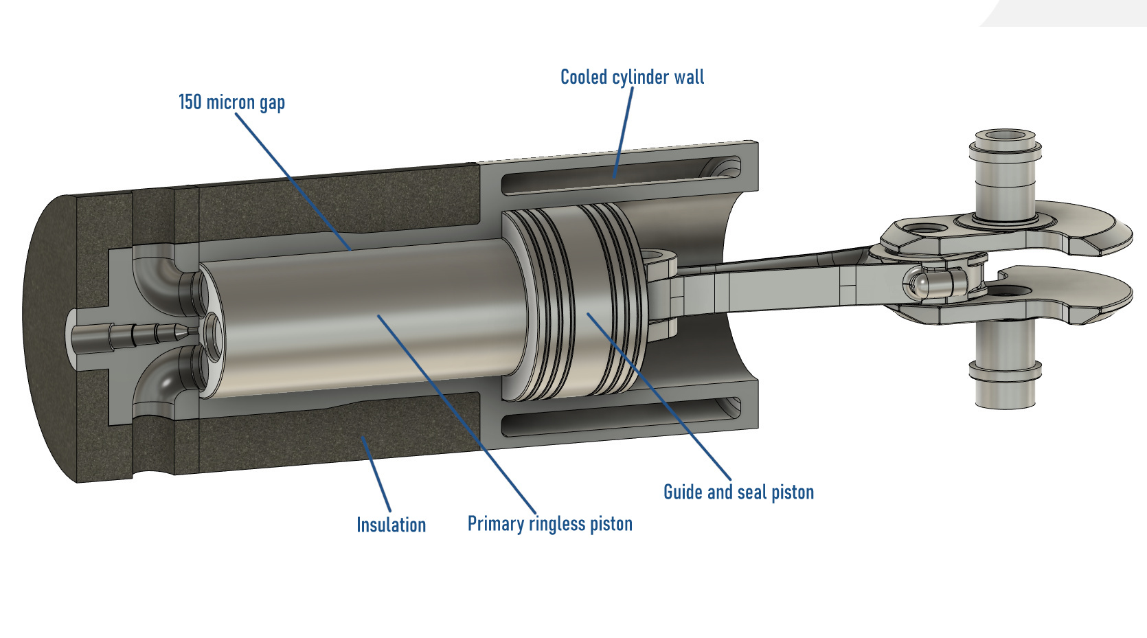
Development of the Minimum-Friction Adiabatic Engine, I. Kubo, S. R. Frisdrf, Cummins Engine Company, Inc., Columbus, Indiana, And, W. Bryzikj, U.S. Army Tank-Automative Command, Warren, Michigan
In the patent: Adiabatic Internal Combustion Engine, US4800853A, Charles E. Kraus, Charles B. Lohr, Excelermatic Inc, a similar arrangement is found, where the heat-exposed piston and combustion chamber are offset from the oil-lubricated seals.
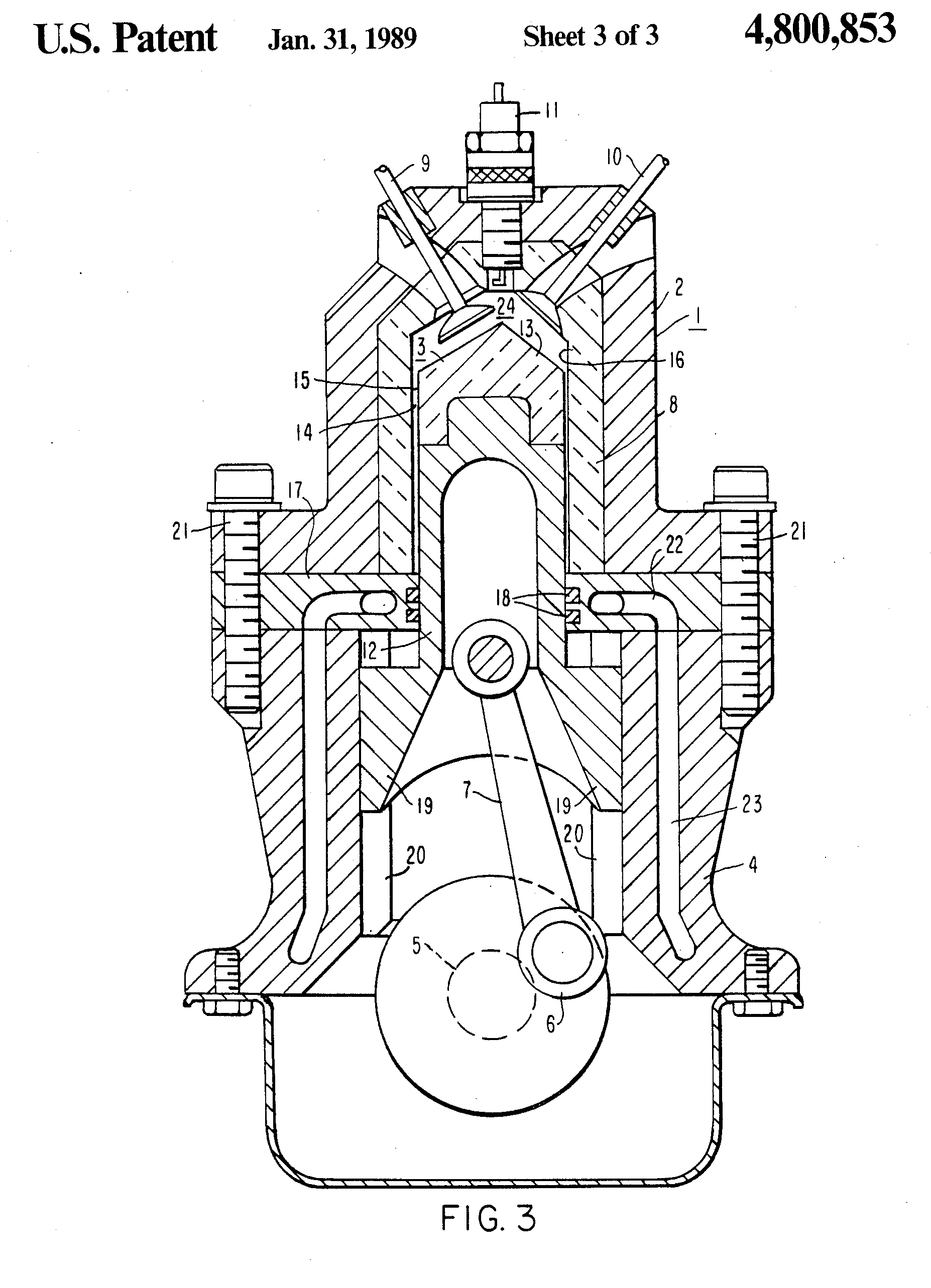
“With this arrangement, the heat-resistant material surfaces of the piston and the cylinder are not in contact with one another and therefore need not be lubricated. Their temperature may therefore be permitted to be very high without causing any damage to the engine’s lubricant. The guide and seal structure of the cylinder wall which contains the seal rings and which is lubricated is sufficiently remote from the center of the combustion chamber so as not to be unduly exposed to the high combustion gas temperatures especially since, by the time the piston reaches its lower end of travel, the combustion gases are sufficiently cooled by expansion and extraction of energy.”
“As such pistons experience no substantial side thrust, and involve no problems of alignment of parts, they may be made to maintain separation from the cylinder by means of a film of air, thus dispensing with lubrication by oil. In the absence of oil lubrication cylinder cooling may be greatly reduced or even dispensed with, thus improving efficiency and simplifying construction.”
Gas-Llubricated Free Piston Engines with Supercharging Arrangements, US2983098A, Bush Vannevar, 1955
Gas-lubricated piston machine, DE3447459A1, Hartmut Prof. Dr.-Ing, Hensel Karsten Dipl.-Ing. Laing Oliver Dipl.-Phys, 1984
“The piston of a gas-lubricated piston machine is rotatably connected to a pushrod or a connecting rod. In order to build up a supporting gas film even during the dead center periods, the piston is made to rotate rapidly in relation to the cylinder wall. The pushrod of a two-stage piston machine can also be rotatably pivoted on the piston of the second stage so that the power-stroke forces of the two pistons are transmitted by the connecting rod of the second stage to the crank mechanism.”
“A gas lubrication structure is provided with a high-temperature-side cylinder, an expansion piston lubricated relative to the high-temperature-side cylinder by gas, and a layer provided to the outer peripheral surface of the expansion piston and composed of a material flexible and having a higher linear expansion coefficient than the base material of the expansion piston. The thickness of the layer under normal temperatures is not less than the size of the clearance formed between the layer and the high-temperature-side cylinder. Also, even if the layer is thermally expanded under use conditions, the layer under normal temperatures has a thickness enabling a clearance to be formed between the layer and the high-temperature-side cylinder.”
Gas Lubrication Structure for Piston, and Stirling Engine, US8763514B2, Hiroshi Yaguchi, Daisaku Sawada, Masaaki Katayama, Toyota Motor Corp, 2009
Oilless and Uncooled Diesel Engine Without Piston Rings With Adiabatic Operation, DE19651069C2, Lothar Strach
Engine cylinder and piston for an uncooled internal combustion engine, especially for a four-stroke diesel engine with exhaust turbocharger, DE3643828A1, Hubert Dr Grieb, MTU Aero Engines GmbH
Uncooled Oilless Internal Combustion Engine Having Uniform Gas Squeeze Film Lubrication, EP0330326B1, Wallace R. Wade, Vemulapalli Durga Nageswar Rao, Peter H. Havstad, Ford Werke GmbH
The Romance of Engines, by Suzuki, Takashi, 1997, SAE
The Adiabatic Engine for Advanced Automotive Applications, Roy Kamo, Adiabatics, Inc, Columbus, Indiana, USA

 CHRISTOPHE De RIVALS MAZERES